Note
Access to this page requires authorization. You can try signing in or changing directories.
Access to this page requires authorization. You can try changing directories.
Warning
Review the General Safety Precautions and Battery Safety guidelines in their entirety before proceeding with any repair steps.
Important
Read this Guide in its entirety before starting any repairs. If at any point you're unsure or uncomfortable about performing the repairs, as detailed in this Guide, DO NOT proceed. Contact Microsoft for more support options.
Warning
Failure to follow the instructions in this Guide, use of non-Microsoft (nongenuine), incompatible, or modified replacement parts, and/or failure to use proper tools could result in serious injury, death, and/or damage to the product or other property.
Prerequisite Steps
Steps outlined in this section should be conducted before starting any repair on a Surface device.
Power off device – Ensure the device is powered off completely and the battery has been fully discharged. Refer to the Repair-specific precautions and warnings section for guidelines. Once discharged, the device should be disconnected from all power sources.
ESD Prevention – Ensure ESD prevention steps and general guidelines are followed before opening the device. Refer to the ESD Prevention section for guidelines.
Position Device – To prevent damage to the device, ensure the device is placed on a clean surface free of debris.
Kickstand Replacement Process
Preliminary Requirements
Important
Be sure to follow all special (bolded) notes of caution within each process section.
Required Tools and Components
- All tools required for repair are listed under Service Tools and Jigs.
- All parts required for this repair will be provided in the CRU kit being purchased. CRU kits are listed on the Illustrated Parts List.
Prerequisite Steps
- Power Off Device – Ensure device is powered off by fully discharging the battery. Refer to Repair-specific precautions and warnings section for details. Ensure device is disconnected from a power supply and all cables and drives are removed.
- ESD Prevention – Check to make sure that general guidelines and ESD Prevention steps are followed before opening device. Refer to ESD Prevention section for details.
Procedure – Removal (Kickstand)
Place device screen-down on soft ESD-safe mat – Ensure mat is clear of any abrasive material that might scratch the Touch Display Module (display) glass.
Extend the kickstand to approximately 90-degrees.
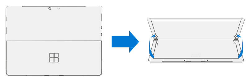
Remove Hinge Screws – Use your finger to hold the back of the kickstand behind the hinge while removing the Kickstand Screws using a T4 (Torx) driver. One screw for each hinge. Ensure screws don't fall into the hinge opening.

Angle Kickstand Down – Firmly grip the hinges and the kickstand between thumb and index fingers. Rotate the kickstand from 90 degrees to approximately 45 degrees.

Release Kickstand Threaded Bosses – Using fingers on the underside of the kickstand and thumb on the topside, slightly rotate the kickstand about the axis as shown. The kickstand should rotate ~5 degrees to free the two threaded bosses of the kickstand from the recesses of the hinges.

Remove Kickstand – Using the palm of your hand, firmly hold the device down from the center of the chassis. Simultaneously, grip the kickstand off-center between your thumb and index finger and firmly pull. Pull with a moderate amount of force until the foam inserts slide out of the device. If the kickstand is stuck, ensure the threaded bosses have not slipped back into the recess on the hinges.

Warning
Inspect Removed Kickstand Foam Tabs – Damaged foam or tabs can't be safely removed. Attempts to do so can damage internal components. Don't insert anything other than the tabs into the slots. Ensure both tabs are complete and show no signs of tearing. Don't attempt to remove it from the interior of the device, instead proceed to Procedure – Removal (Chassis) to replace the old chassis.

Procedure – Installation (Kickstand)
Important
Use caution when handling new kickstand assembly to avoid cosmetic damage of the kickstand and the device.
- Insert Foam Tabs – With the hinges still at ~ 45-degrees start to slide the new kickstand’s foam tabs into the slots on the back of the chassis. Foam should slide in with minimal force – don't crumple the foam by using excess force. Don't slide the foam completely into the device – insert the foam tabs until ~3/4 of the foam tabs are inside the device.
Important
Don't use any tool or sharp object to assist inserting the tabs into the slots. Only the tabs should be inserted. Doing so could damage internal components.

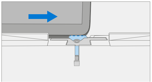
Slot Outer Lip of Hinge Into Kickstand – Using fingers on the underside of the kickstand and thumb on the topside, slightly rotate the kickstand about the axis as shown. The kickstand should rotate ~5-degrees to catch the outer lip of the hinge. Push the kickstand toward the device.
Slip Kickstand Threaded Bosses Into Hinge Recesses – Maintaining pressure on the kickstand to prevent it from backing out, rotate the kickstand down into place (Figure 7-9). The threaded bosses of the kickstand should slip into the recesses of the hinges.

Rotate the Kickstand Up – Firmly grip the hinges and the kickstand between thumb and index fingers as shown. Rotate the kickstand from 45-degrees to approximately 90-degrees.

Apply Thread Locker to Screws – Brush new MM16022I000 screws with Loctite 649 Activator. Let screws sit for 2 minutes after activator is applied before assembling to device.

Apply Thread Locker to Screw Bosses – Apply one drop of Loctite 243 thread locker to each screw boss.

Install Hinge Screws – Use your finger to hold the back of the kickstand behind the hinge while installing 4 MM16022I000 screws using a T4 Torx driver until they're fully seated. Ensure the kickstand is properly aligned and seated in the hinges, then tighten the screws an extra ~quarter turn (~ 90-degrees). Be careful to tighten the screws only until snug and not to strip the kickstand threads. Ensure screws don't fall into hinge opening.

Final Kickstand Installation Inspection – Fold down the kickstand and peel off protective plastic from the kickstand and logo if present. Verify the side edges of the kickstand are aligned with the midframe walls and that there are no obvious steps/gaps between the kickstand and the chassis. Wipe the device thoroughly (including under the kickstand) with the microfiber cloth to remove all fingerprints.
Display Replacement Process
Preliminary Requirements
Important
Be sure to follow all special (bolded) notes, cautions, & warnings in each process section.
Required Tools and Components
- All tools required for repair are listed under Service Tools and Jigs.
- All parts required for this repair will be provided in the CRU kit being purchased. CRU kits are listed on the Illustrated Parts List.
Prerequisite Steps
- Prep Device – Device must be set in Display Replacement Mode before
removing a faulty display.
Connect software tools USB drive – Use SDT to USB connector on device under repair.
Connect power supply to device.
Power on device – Depress the power button on the side of the device.
Run software tool – At the device OS, use Windows Explorer, navigate to USB drive and run:
SDT – Select Repair setup and validation. Run the Touch Display Setup. At the end of the tool process device will power down.
Important
The device must first be set in Display Replacement Mode before broken/defective display is removed from the device. Software tools are provided for this purpose. Device must be functional to the point that software tools can be run on device from within the Windows OS. If display on device is non- functional, there's no display, or it's unreadable, connect an external PC monitor and keyboard to the device’s USB C port or Surflink port. If this can't be completed, then the device isn't a good candidate for repair.
Important
This step must be conducted on the device successfully before removal of a faulty display. Ensure light levels in the work area remain consistent during the touch display setup process.
Warning
Don't use a heat gun or hair dryer to debond display
- Power Off Device – Ensure device is powered off by fully discharging the battery. Refer to Repair-specific precautions and warnings section for details. Ensure device is disconnected from a power supply and all cables and drives are removed.
- ESD Prevention – Check to make sure that general guidelines and ESD Prevention steps are followed before opening device. Refer to ESD Prevention section for details.
Procedure - Removal (Display)
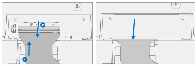
Speaker Mesh Preparation – Place the device face up on a Soft ESD safe mat. Use an iFixit opening tool to widen the gap between the right speaker mesh and device. Push the sharp edge into the gap and side to side along the device edge. Once the flat tip fits fully in the gap, use it to push the speaker mesh towards the device, repeating uniformly along the length of the speaker mesh. The metal mesh will either fold lengthwise or slide completely under the glass. Repeat this process for left speaker mesh.

Mark Display Debonding Tool Pick Depth – To prevent damage to internal components use a metric ruler to draw a 2-mm mark and 8-mm mark on the plastic pick.

Display Debonding Tool
- Install marked pick in the holder with the marks in view. Use a 3 mm Allen Driver to adjust pick height to the lowest setting.

- Clamp debonding tool to edge of workbench. Ensure the cut depth adjustment can be accessed while the tool is clamped down.

- Place the right-side speaker edge of the device in the debonding tool above the pick. Adjust the pick height to the 2-mm mark. Ensure it enters the gap between the display and bucket edge.

- With both hands, draw the right side of the device through the debonding tool track.

- At the bottom right corner, rotate the device in the debonding tool track. Draw the bottom side of the device through the debonding tool track.

- At the bottom left corner, rotate the device in the debonding tool track. Draw the left side of the device through the debonding tool track.

- At the top left corner, rotate the device in the debonding tool track. Draw the top side of the device through the debonding tool track.

- Place the top left edge of the device in the debonding tool track. Adjust the pick height to the 8-mm mark. Ensure it enters the gap between the display and bucket edge. With both hands, draw the top edge of the device through the debonding tool track.
Important
Don't insert the pick more than 2 mm along the left and right sides or bottom edge of the display. The pick depth shouldn't exceed 8 mm along the top edge of the display

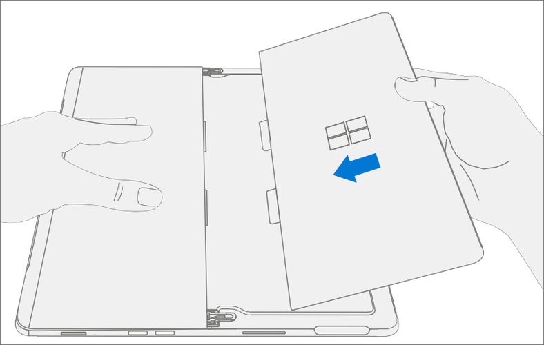
- Separate Display From Chassis – Gently pull up vertically on the top edge of the glass while pushing down on the chassis to separate the glass. Lift the edges of the display and inspect for any remaining adhesive. Slice or remove (with an iFixit Pick) any strands still connecting the display to the chassis.
Warning
It's recommended a Microsoft provided ESD-safe battery cover appropriate for size be placed across the device to protect the battery from any accidental damage during repair. Ensure corners of cover are always aligned with the corners of the device during repair. If battery cover is misaligned during the repair operation in any way, realign before continuing repair activities.
- Disconnect Display Connector – Lay the display down gently next to the chassis on the work surface. Remove the shield lid on the motherboard connector by inserting the flat end of a spudger underneath the inner edge of the shield. Then gently pry upwards and the shield will come off. Disconnect the display connector using the pointed end of a spudger.
Warning
Don't pull on the Display FPC to disconnect the display.
Warning
Take care not to puncture or press on the battery when removing connectors. See Battery Safety for additional information.

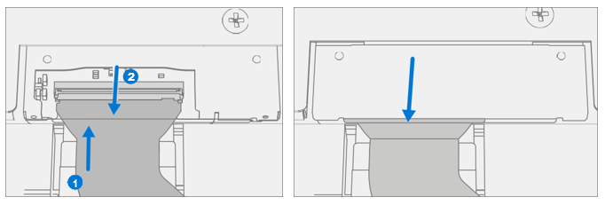
Remove Speaker Mesh From Chassis – Remove any remaining speaker mesh from the chassis. Use a handheld pick to remove it by inserting the pick between the Speaker mesh and the enclosure. Confirm a successful removal of the speaker mesh and its adhesive by verifying the three cutouts of the chassis are exposed.

Remove Residual Adhesive – Using IPA and cotton swabs clean residual PSA off the chassis. Ensure area around the Camera and IR Sensor is clean and free of any dust or other contamination. Wipe the area around the camera with a lint free cloth.

Procedure - Installation (Display)
- Pre-Installation Device Inspection
Warning
Verify the battery’s condition. Devices exhibiting battery issues as outlined in the Battery Inspection Process require whole unit replacement.
Important
Leave protective cling on new display during all installation steps.
Important
Carefully inspect the internal areas of the bucket. Ensure the area around battery is free of any foreign objects.
Display Adhesive Application – Thoroughly clean the chassis along the display PSA bonding surface using IPA and a cotton swab. Wait at least 30 seconds before applying the new PSA. Apply the 4 strips of PSA to the chassis. Align the PSA following the outline on the chassis. Leave the blue liner on the PSA, it is removed at a later step. Refer to the illustration for PSA locations.

Speaker Mesh Application – Place the display face-down on a Soft ESD safe mat. Wipe down the outer edges of the display with a lint free cloth. When installing the originally removed display ensure outer edges are clean and clear of PSA residue. Remove the protective liner from the speaker mesh. Using the clear handle, align the speaker mesh into the chassis speaker opening. Press onto the mesh for 10 seconds to activate the adhesive. Carefully remove the clear handle. Repeat this process for the other side of the chassis.

Final Inspection – Before continuing with the reassembly, inspect the device internals to ensure no screws, foam, tape, or other foreign material has been misplaced. If any damage is observed to the battery, contact Microsoft for a device exchange.
Connect Display Connector – While supporting the display with one hand, connect the Display FPC by pressing it into the mating connector on the motherboard, then press down on the locking tab. Install a new shield over the Display FPC. Ensure all edges of the shield are snapped into place.
Apply Display to Chassis – Hold the display and remove the PSA Liners to expose adhesive. Turn the display over and place it on the chassis. Align the display along the top edge first (Toe-in) and lower after alignment is found. Ensure that the glass sits flush in the chassis and doesn't rest anywhere on top of the chassis lip.

Bond Adhesive – Place the bonding frame on the device, ensuring that the cutouts on the sides line up with the volume/power buttons. Place foam pad over bonding frame. Place 22.5 kg of weight on top of the foam pad and bonding fame. Leave weight in place for 2 minutes.
Important
Weight Requirement:
Minimum 22.5 kg (50 lbs.) / Maximum 30 kg (66 lbs.) Minimum
Dimensions: 280mm x 200mm
Geometry must be symmetrical, to allow for even weight distribution. Weight used must be a flat plate, with consistent flatness and not protrude from contact plane with Bonding Frame.
Weight must contact the full perimeter of the frame when placed above it. Recommended weights (Ruck Plates of 9 kg + 14 kg, or 20 lbs. + 30 lbs.)
When using Ruck weights place the 14-kg weight first, then stack the 9-kg weight on top. Ensure foam pad covers entire bonding frame.

- After Bonding Inspection – Remove the weights, foam pad, and the frame. Lift carefully to avoid damaging the device. Inspect the display for scratches, cracks, large gaps, and its flushness with respect to the chassis.
- New Display Calibration – On installation of a new display device
final calibration relies on the successful completion of the display
Replacement Mode. Display calibration isn't required when
installing the originally removed display.
- Connect software tools USB drive with SDT to USB connector on device under repair.
- Power on device – Depress the power button on the side of the device.
- Perform Setup
- Run software tool – At the device OS, use Windows Explorer, navigate to USB drive, and run: SDT – Select Repair setup and validation. Run the Touch Display Calibration. Accept the restart prompt at the end of the tool process.
Important
This step must be conducted on the device successfully on installation of a new display or when installing any display onto a new motherboard. Ensure light levels in the work area remain consistent during the touch display calibration process. Any tool failures require restarting the process with a new display.
- Run SDT – Power on device and connect USB drive with SDT Configuration Files. Run SDT to ensure all device features and functions operate as expected.
- Final Display Installation Inspection – Remove protective cling from the new display. Verify the side edges of the display are flush, and that there are no obvious steps/gaps between the display and the chassis. Wipe the device thoroughly (including under the kickstand) with the microfiber cloth to remove all fingerprints.
Procedure – Alternate Installation (Display)
- Pre-Installation Device Inspection
Warning
Verify the battery’s condition. Devices exhibiting battery issues as outlined in the Battery Inspection Process require whole unit replacement.
Important
Leave protective cling on new Display during all installation steps.
Important
Carefully inspect the internal areas of the bucket. Ensure the area around battery is free of any foreign objects.
Display Adhesive Application – Thoroughly clean the chassis along the display PSA bonding surface using IPA and a cotton swab. Wait at least 30 seconds before applying the new PSA. Apply the 4 strips of PSA to the chassis. Align the PSA following the outline on the chassis. Leave the blue liner on the PSA, it is removed at a later step. Refer to the illustration for PSA locations.

Speaker Mesh Application – Place the display face-down on a Soft ESD safe mat. Wipe down the outer edges of the display with a lint free cloth. When installing the originally removed display ensure outer edges are clean and clear of PSA residue. Remove the protective liner from the speaker mesh. Using the clear handle, align the speaker mesh into the chassis speaker opening. Press onto the mesh for 10 seconds to activate the adhesive. Carefully remove the clear handle. Repeat this process for the other side of the chassis.

Connect Display Connector – While supporting the display with one hand, connect the Display FPC by pressing it into the mating connector on the motherboard, then press down on the locking tab. Install a new shield over the Display FPC. Ensure all edges of the shield are snapped into place.
Apply Display to Chassis – Hold the display and remove the PSA Liners to expose adhesive. Turn the display over and place it on the chassis. Align the display along the top edge first (Toe-in) and lower after alignment is found. Ensure that the glass sits flush in the chassis and doesn't rest anywhere on top of the chassis lip. Lightly press on the edges of the display to create an initial bond.

Alternate Bonding PSA – Bonding is a multi-step process. Refer to the illustrations.
Important
Use steel shot bags, one 9 kg, and one 14 kg. Apply the 1st 9-kg bag, then the 14-kg bag.

- After Bonding Inspection – Remove the steel shot bags and lift device out of the frame. Lift carefully to avoid damaging the device. Inspect the display for scratches, cracks, large gaps, and its flushness with respect to the chassis.
- New Display Calibration – On installation of a new display
device final calibration relies on the successful completion of the
Display Replacement Mode. Display calibration isn't required when
installing the originally removed display.
- Connect software tools USB drive with SDT to USB connector on device under repair.
- Power on device – Depress the power button on the side of the device.
- Run software tool – At the device OS, use Windows Explorer, navigate to USB drive, and run: SDT – Select Repair setup and validation. Run the Touch Display Calibration. Accept the restart prompt at the end of the tool process.
Important
This step must be conducted on the device successfully on installation of a new display or when installing any display onto a new motherboard. Ensure light levels in the work area remain consistent during the touch display calibration process. Any tool failures require restarting the process with a new display.
- Run SDT – Run SDT to ensure all device features and functions operate as expected.
- Final Display Installation Inspection – Remove protective cling from the display. Verify the side edges of the display are flush, and that there are no obvious steps/gaps between the display and the chassis. Wipe the device thoroughly (including under the kickstand) with the microfiber cloth to remove all fingerprints.
SD Slot Replacement Process
Preliminary Requirements
Important
Be sure to follow all special (bolded) notes of caution within each process section.
Required Tools and Components
- All tools required for repair are listed under Service Tools and Jigs.
- All parts required for this repair will be provided in the CRU kit being purchased. CRU kits are listed on the Illustrated Parts List.
Prerequisite Steps
- Power Off Device – Ensure device is powered off by fully discharging the battery. Refer to Repair-specific precautions and warnings section for details. Ensure device is disconnected from a power supply and all cables and drives are removed.
- ESD Prevention – Check to make sure that general guidelines and ESD Prevention steps are followed before opening device. Refer to ESD Prevention section for details.
- Remove Display – Remove the display as detailed in the Procedure - Removal (Display).
Procedure - Removal (SD Slot)
Important
There are foams around the SD slot that reduce emissions from the device. Don't remove this foam as it is critical for emissions compliance.
Warning
Take care not to puncture or press on the battery when removing connectors or shields. See Battery Safety for additional information.
Remove Shield – Using a plastic spudger remove the shield highlighted.

Disconnect SD Slot Connector – Disconnect the FPC for the SD slot using a plastic spudger by lifting black tab then pulling the connector from the socket. and

Remove Screws – Using a T3 Torx driver remove the two highlighted screws. Lift card slot out of chassis.

Procedure - Installation (SD Slot)
Important
There are foams around the SD slot that reduce emissions from the device. Don't remove this foam as it is critical for emissions compliance.
Install SD Slot and Screws – Using your fingers place SD slot in chassis. Using a T3 Torx driver install 2 new MS16020I300 screws. Tighten both screws until snug then turn another 45-degrees (1/8 turn) or until fully fastened.

Connect SD Slot – Connect the FPC for the SD slot into the socket on the motherboard. Once fully inserted, press down on locking tab.

Install Shield – Place shield over frame on motherboard. Press down along all edges, snapping them into place.
Install Display – Install the display as detailed in the Procedure – Installation Display
Run SDT – Power on device and connect USB drive with SDT Configuration Files. Run SDT to ensure all device features and functions operate as expected.
Blade Connector Replacement Process
Preliminary Requirements
Important
Be sure to follow all special (bolded) notes of caution within each process section.
Required Tools and Components
- All tools required for repair are listed under Service Tools and Jigs.
- All parts required for this repair will be provided in the CRU kit being purchased. CRU kits are listed on the Illustrated Parts List.
Prerequisite Steps
- Power Off Device – Ensure device is powered off by fully discharging the battery. Refer to Repair-specific precautions and warnings section for details. Ensure device is disconnected from a power supply and all cables and drives are removed.
- ESD Prevention – Check to make sure that general guidelines and ESD Prevention steps are followed before opening device. Refer to ESD Prevention section for details.
- Remove Display – Remove the display as detailed in the Procedure - Removal (Displa).
- Remove SD Slot – Follow steps for Procedure - Removal (SD Slot).
Procedure - Removal (Blade Connector)
Warning
Take care not to puncture or press on the battery when removing connectors or shields. See Battery Safety. for additional information.
Remove Shield – Using a plastic spudger remove the shield highlighted.

Disconnect SD Slot Connector – Disconnect the FPC for the SD slot using a plastic spudger by lifting black tab then pulling the connector from the socket. and

Disconnect Blade Connector – Disconnect the FPC for the Blade Connector using a plastic spudger by lifting black tab then pulling the connector from the socket.

Remove Screws – Using a T3 Torx driver remove the two highlighted screws. Lift connector out of chassis.

Procedure - Installation (Blade Connector)
Install Blade Connector – Place connector into chassis, aligning screw holes with holes in the chassis. Using a T3 Torx driver install 2 new MS16020I400 screws and tighten each screw until snug then turn another 45-degrees (1/8 turn) or until fully fastened.
Connect Blade Connector – Connect the FPC for the Blade Connector into the socket on the motherboard. Once fully inserted, press down on locking tab.

Connect SD Slot – Connect the FPC for the SD slot into the socket on the motherboard. Once fully inserted, press down on locking tab.

Install Shield – Place shield over frame on motherboard. Press down along all edges, snapping them into place.

Install Display – Install the display as detailed in the Procedure - Installation (Display).
Run SDT – Power on device and connect USB drive with SDT Configuration Files. Run SDT to ensure all device features and functions operate as expected.
Antenna Deck Replacement Process
Preliminary Requirements
Important
Be sure to follow all special (bolded) notes of caution within each process section.
Required Tools and Components
- All tools required for repair are listed under Service Tools and Jigs.
- All parts required for this repair will be provided in the CRU kit being purchased. CRU kits are listed on the Illustrated Parts List.
Prerequisite Steps
- Power Off Device – Ensure device is powered off by fully discharging the battery. Refer to Repair-specific precautions and warnings section for details. Ensure device is disconnected from a power supply and all cables and drives are removed.
- ESD Prevention – Check to make sure that general guidelines and ESD Prevention steps are followed before opening device. Refer to ESD Prevention section for details.
- Remove Display – Remove the display as detailed in the Procedure - Removal (Display).
Procedure - Removal (Antenna Deck)
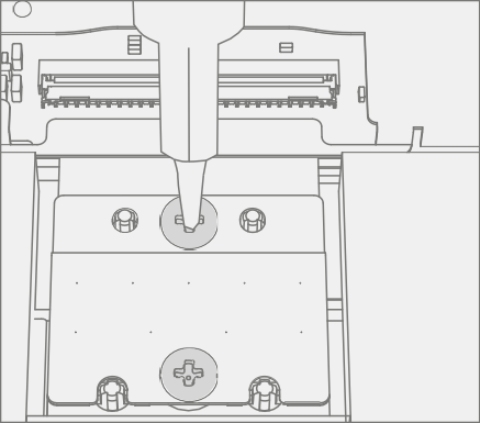
Remove Screws – Using a PH0 Phillips driver remove the 6 screws on the antenna deck. Lift the deck out of the chassis and set aside. Retain Antenna deck for future reinstallation.

Procedure - Installation (Antenna Deck)
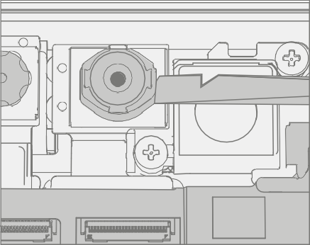
Install Antenna Deck Screws – Place antenna deck over front camera. Using a PH0 Phillips driver install 6 new MS16030I640 screws. Tighten each screw until snug in the order (beginning with 1 and ending with 6 as detailed in the image) then turn another 45-degrees (1/8 turn) or until fully fastened.

Install Display – Install the display as detailed in the Procedure - Installation (Display).
Run SDT – Power on device and connect USB drive with SDT Configuration Files. Run SDT to ensure all device features and functions operate as expected.
Rear Camera Replacement Process
Preliminary Requirements
Important
Be sure to follow all special (bolded) notes of caution within each process section.
Required Tools and Components
- All tools required for repair are listed under Service Tools and Jigs.
- All parts required for this repair will be provided in the CRU kit being purchased. CRU kits are listed on the Illustrated Parts List.
Prerequisite Steps
- Power Off Device – Ensure device is powered off by fully discharging the battery. Refer to Repair-specific precautions and warnings section for details. Ensure device is disconnected from a power supply and all cables and drives are removed.
- ESD Prevention – Check to make sure that general guidelines and ESD Prevention steps are followed before opening device. Refer to ESD Prevention section for details.
- Remove Display – Remove the display as detailed in the Procedure - Removal (Display).
- Remove Antenna Deck – Follow steps for Procedure - Removal (Antenna Deck).
Procedure - Removal (Rear Camera)
Remove Shield – Use a plastic spudger to remove the shield covering the camera connectors.

Disconnect Camera Connector – Disconnect the FPC for the rear camera using a plastic spudger by lifting black tab then pulling the connector from the socket.

Remove Rear Camera – Using a PH0 Phillips driver remove the two screws securing the camera to the chassis. Then, using a spudger, lift out the rear camera.

Procedure - Installation (Rear Camera)
Install Rear Camera – Clean lens with microfiber cloth. Then, using your fingers, gently place rear camera in the chassis. Using a PH0 Phillips driver tighten install 2 new MS16020I300 screws. Tighten until snug then turn another 45-degrees (1/8 turn) or until fully fastened.

Connect Rear Camera – Connect the FPC for the rear camera into the socket on the motherboard. Once fully inserted, press down on locking tab.

Install Antenna Deck – Install the antenna deck as detailed in the Procedure - Installation (Antenna Deck).
Install Display – Install the display as detailed in the Procedure - Installation (Display).
Run SDT – Power on device and connect USB drive with SDT Configuration Files. Run SDT to ensure all device features and functions operate as expected. If no further repairs are required proceed to final steps.
Front Camera Replacement Process
Preliminary Requirements
Important
Be sure to follow all special (bolded) notes of caution within each process section.
Required Tools and Components
- All tools required for repair are listed under Service Tools and Jigs.
- All parts required for this repair will be provided in the CRU kit being purchased. CRU kits are listed on the Illustrated Parts List .
Prerequisite Steps
- Power Off Device – Ensure device is powered off by fully discharging the battery. Refer to Repair-specific precautions and warnings section for details. Ensure device is disconnected from a power supply and all cables and drives are removed.
- ESD Prevention – Check to make sure that general guidelines and ESD Prevention steps are followed before opening device. Refer to ESD Prevention section for details.
- Remove Display – Remove the display as detailed in the Procedure - Removal (Display).
- Remove Antenna Deck – Follow steps for Procedure - Removal (Antenna Deck).
- Remove Rear Camera – Follow steps for Procedure - Removal (Rear Camera).
Procedure - Removal (Front Camera)
Disconnect Camera Connector – Disconnect the FPC for the front camera using a plastic

Remove Front Camera – Using a plastic spudger lift out the front camera.
Procedure - Installation (Front Camera)
Install Front Camera – Using your fingers gently place front camera on aligning posts. Clean lens with microfiber cloth.

Connect Front Camera – Connect the FPC for the front camera into the socket on the motherboard. Once fully inserted, press down on locking tab.

Clean Camera – Using a microfiber cloth, clean the lens of the front camera.
Install Rear Camera – Install the rear camera as detailed in the Procedure - Installation (Rear Camera).
Install Antenna Deck – Install the antenna deck as detailed in the Procedure - Installation (Antenna Deck).
Install Display – Install the display as detailed in the Procedure - Installation (Display)
Run SDT – Power on device and connect USB drive with SDT Configuration Files. Run SDT to ensure all device features and functions operate as expected.
IR Camera Replacement Process
Preliminary Requirements
Important
Be sure to follow all special (bolded) notes of caution within each process section.
Required Tools and Components
- All tools required for repair are listed under Service Tools and Jigs.
- All parts required for this repair will be provided in the CRU kit being purchased. CRU kits are listed on the Illustrated Parts List.
Prerequisite Steps
- Power Off Device – Ensure device is powered off by fully discharging the battery. Refer to Repair-specific precautions and warnings section for details. Ensure device is disconnected from a power supply and all cables and drives are removed.
- ESD Prevention – Check to make sure that general guidelines and ESD Prevention steps are followed before opening device. Refer to ESD Prevention section for details.
- Remove Display – Remove the display as detailed in the Procedure - Removal (Display).
- Remove Antenna Deck – Follow steps for Procedure - Removal (Antenna Deck).
- Remove Rear Camera – Follow steps for Procedure - Removal (Rear Camera).
Procedure - Removal (IR Camera)
Disconnect Camera Connector – Disconnect the FPC for the IR camera using a plastic spudger by lifting black tab then pulling the connector from the socket. and

Remove IR Camera – Using a plastic spudger lift out the IR camera.

Procedure - Installation (IR Camera)
Install IR Camera – Using your fingers gently place camera on aligning posts. Clean lens with microfiber cloth.

Connect IR Camera – Connect the FPC for the camera into the socket on the motherboard. Once fully inserted, press down on locking tab.

Clean Camera – Using a microfiber cloth, clean the lens of the front camera.
Install Rear Camera – Install the rear camera as detailed in the Procedure – Installation (Rear Camera).
Install Antenna Deck – Install the antenna deck as detailed in the Procedure - Installation (Antenna Deck).
Install Display – Install the display as detailed in the Procedure - Installation (Display).
Run SDT – Power on device and connect USB drive with SDT Configuration Files. Run SDT to ensure all device features and functions operate as expected.
Motherboard Replacement Process
Preliminary Requirements
Important
Be sure to follow all special (bolded) notes of caution within each process section.
Required Tools and Components
- All tools required for repair are listed under Service Tools and Jigs.
- All parts required for this repair will be provided in the CRU kit being purchased. CRU kits are listed on the Illustrated Parts List.
Prerequisite Steps
Important
If replacing both the Motherboard and Display, complete the Motherboard repair first and ensure functionality before beginning the Display replacement procedure. Failure to do so might result in TDM functionality being impacted.
- Prep Device – Device must be set in Display Replacement Mode before
removing a faulty display.
- Connect software tools USB drive – Use SDT to USB connector on device under repair.
- Connect power supply to device.
- Power on device – Depress the power button on the side of the device.
- Run software tool – At the device OS, use Windows Explorer, navigate to USB drive and run: SDT – Select Repair setup and validation. Run the Touch Display Setup. At the end of the tool process device will power down.
Important
This step must be conducted on the device successfully before removal of a faulty display. Ensure light levels in the work area remain consistent during the touch display setup process.
- Power Off Device – Ensure device is powered off by fully discharging the battery. Refer to Repair-specific precautions and warnings section for details. Ensure device is disconnected from a power supply and all cables and drives are removed.
- ESD Prevention – Check to make sure that general guidelines and ESD Prevention steps are followed before opening device. Refer to ESD Prevention section for details.
- Remove Display – Remove the display as detailed in the Procedure - Removal (Display).
- Remove Antenna Deck – Follow steps for Procedure - Removal (Antenna Deck).
- Remove Rear Camera – Follow steps for Procedure - Removal (Rear Camera).
- Remove Front Camera – Follow steps for Procedure - Removal (Front Camera).
- Remove IR Camera – Follow steps for Procedure - Removal (IR Camera).
Procedure - Removal (Motherboard)
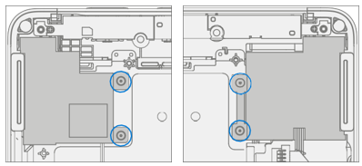
Disconnect Battery – Using a PH0 Phillips driver remove the 2 Battery Bracket Screws securing the battery bracket. Lift the bracket away from the motherboard.

Disconnect FPC’s – On the upper right portion of the motherboard use a plastic spudger lift up the locking tab on the Speaker FPC and pull the FPC from the connector. Then push the connector to the right of the previous connector out of its socket.

Remove Shield – Using a plastic spudger remove the shield highlighted.

Disconnect SD Slot Connector – Disconnect the FPC for the SD slot using a plastic spudger by lifting black tab then pulling the connector from the socket.

Disconnect Blade Connector – Disconnect the FPC for the Blade Connector using a plastic spudger by lifting black tab then pulling the connector from the socket.

Remove Screws – Using a PH0 Phillips driver remove the 7 Motherboard Screws securing the motherboard to the chassis.

Remove Motherboard – Lift the left side of the motherboard from the chassis and slide out to the left.
Procedure - Installation (Motherboard)
Install motherboard – Using two hands align screw holes on motherboard with the chassis and place motherboard in the chassis, first aligning the USB connector into the opening and then lowering onto the screw posts in the chassis.

Install screws – Using a PH0 Phillips driver install 7 new MS16015I100 screws as marked, turning each screw until finger tight then tightening by an extra 1/8 turn (45-degrees) or until fully fastened.

Connect FPC’s – On the upper right portion of the motherboard connect the speaker FPC and press down on the locking tab. Then push the connector to the right of the previous connector into its socket.

Connect Blade Connector – Connect the FPC for the Blade Connector into the socket on the motherboard. Once fully inserted, press down on locking tab.

Connect SD Slot – Connect the FPC for the SD slot into the socket on the motherboard. Once fully inserted, press down on locking tab.

Install Shield – Place shield over frame on motherboard. Press down along all edges, snapping them into place.

Connect Battery – Using a PH0 Phillips driver install 2 new MS16020I300 screws securing the battery bracket.
Install IR Camera – Install the thermal module as detailed in the Procedure - Installation (IR Camera).
Install Front Camera – Install the Surflink as detailed in the Procedure - Installation (Front Camera).
Install Rear Camera – Install the Surflink as detailed in the Procedure - Installation (Rear Camera).
Install Antenna Deck – Install the Surflink as detailed in the Procedure - Installation (Antenna Deck)
Install Display – Install the display as detailed in the Procedure - Installation (Display).
Power On Device – Carefully place device top side up. Connect device to power supply, open display, and power on.
Complete Display Calibration
- Connect software tools USB drive with SDT to USB connector on device under repair.
- Run software tool – At the device OS, use Windows Explorer, navigate to USB drive, and run:
SDT – Select Repair setup and validation. Run the Touch Display Calibration. Accept the restart prompt at the end of the tool process.
Important
This step must be conducted on the device successfully on installation of a new motherboard to ensure proper display functionality.
- New Battery Authentication – Ensure the battery reads as authenticated in the Battery Repair (Validation) workflow in SDT. If the battery shows as inauthentic run the SDT Battery Repair (Validation) workflow in its entirety.
- Connect the SDT Configuration USB drive.
- Run the SDT Battery Repair (Validation) to ensure the battery is properly authenticated and all features and functions operate as expected.
Important
Battery authentication requires a stable internet connection. If any battery steps fail retry with a new internet connection. If failures continue reach out to Microsoft Support.
- Run SDT – Power on device and connect USB drive with SDT Configuration Files. Run SDT to ensure all device features and functions operate as expected. If no further repairs are required proceed to final steps.
Speaker Replacement Process
Preliminary Requirements
Important
Be sure to follow all special (bolded) notes of caution within each process section.
Required Tools and Components
- All tools required for repair are listed under Service Tools and Jigs.
- All parts required for this repair will be provided in the CRU kit being purchased. CRU kits are listed on the Illustrated Parts List.
Prerequisite Steps
- Power Off Device – Ensure device is powered off by fully discharging the battery. Refer to Repair-specific precautions and warnings section for details. Ensure device is disconnected from a power supply and all cables and drives are removed.
- ESD Prevention – Check to make sure that general guidelines and ESD Prevention steps are followed before opening device. Refer to ESD Prevention section for details.
- Remove Display – Remove the display as detailed in the Procedure - Removal (Display).
- Remove Antenna Deck – Follow steps for Procedure - Removal (Antenna Deck).
- Remove Rear Camera – Follow steps for Procedure - Removal (Rear Camera).
- Remove Front Camera – Follow steps for Procedure - Removal (Front Camera).
- Remove IR Camera – Follow steps for Procedure - Removal (IR Camera).
- Remove Motherboard – Follow steps for Procedure - Removal (Motherboard).
Procedure - Removal (Speakers)
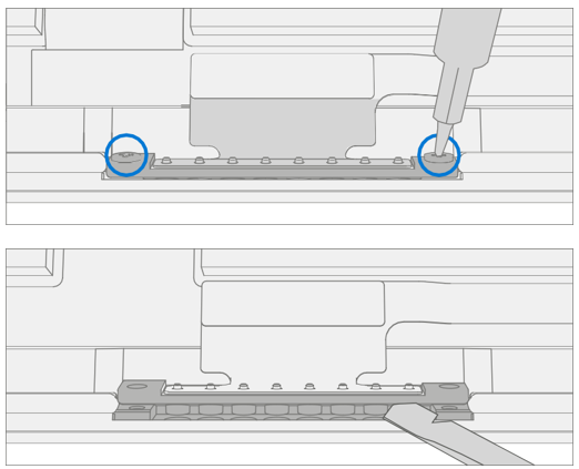
Remove Screws From Speakers – Using a PH0 Phillips driver remove the 2 marked screws each speaker. Lift speakers out of chassis.

Procedure - Installation (Speaker)
Install Speakers – Place speakers in chassis, aligning screw holes. Using a PH0 Phillips driver install the 4 new MM12010I080 screws (2 per speaker) marked, turning each screw until finger tight then tightening by an extra 1/8 turn (45-degrees).
Rout Wire – Route speaker wire through the channel on the chassis.
Important
Failure to route wire properly can cause the wires to be pinched between the chassis and motherboard. This can cause failure in both the speakers and the motherboard. Any damage to the speaker wire requires both speakers to be replaced.

- Install Motherboard – Install the thermal module as detailed in the Procedure - Installation (Motherboard)
- Install IR Camera – Install the thermal module as detailed in the Procedure - Installation (IR Camera)
- Install Front Camera – Install the Surflink as detailed in the Procedure - Installation (Front Camera)
- Install Rear Camera – Install the Surflink as detailed in the Procedure - Installation (Rear Camera)
- Install Antenna Deck – Install the Surflink as detailed in the Procedure - Installation (Antenna Deck)
- Install Display – Install the display as detailed in the Procedure - Installation (Display)
- Run SDT – Power on device and connect USB drive with SDT Configuration Files. Run SDT to ensure all device features and functions operate as expected. If no further repairs are required proceed to final steps.
Chassis + Battery Replacement Process
Preliminary Requirements
Important
Be sure to follow all special (bolded) notes of caution within each process section.
Required Tools and Components
- All tools required for repair are listed under Service Tools and Jigs.
- All parts required for this repair will be provided in the CRU kit being purchased. CRU kits are listed on the Illustrated Parts List.
Prerequisite Steps
- Device Serial Number Notation – The serial number for this device model is located on its original cover. To keep track of the device’s serial number, please record it using waterproof ink on a sticker or label and apply the sticker or label to an easily accessible area on the device exterior. The serial number can't be added permanently to a replacement part. Microsoft might have provided a label for this use in the replacement part’s packaging.
- Power Off Device – Ensure device is powered off by fully discharging the battery. Refer to Repair-specific precautions and warnings section for details. Ensure device is disconnected from a power supply and all cables and drives are removed.
- ESD Prevention – Check to make sure that general guidelines and ESD Prevention steps are followed before opening device. Refer to ESD Prevention section for details.
- Remove Display – Remove the display as detailed in the Procedure - Removal (Display)
- Remove Antenna Deck – Follow steps for Procedure - Removal (Antenna Deck).
- Remove Rear Camera – Follow steps for Procedure - Removal (Rear Camera).
- Remove Front Camera – Follow steps for Procedure - Removal (Front Camera).
- Remove IR Camera – Follow steps for Procedure - Removal (IR Camera).
- Remove SD Slot – Follow steps for Procedure - Removal (SD Slot).
- Remove Blade Connector – Follow steps for Procedure - Removal (Blade Connector).
- Remove Motherboard – Follow steps for Procedure - Removal (Motherboard Camera).
- Remove Speakers – Follow steps for Procedure - Removal (Speakers).
Procedure – Removal (Chassis + Battery)
Prepare Parts – Follow all removal steps in the Prerequisite Steps section of this chapter.
Remove Hinges – Using a T5 Torx driver remove the two Hinge Screws securing the left and right hinges to the chassis.

Procedure – Installation (Chassis + Battery)
Install Hinges – Using a T5 Torx driver install 4 New MS160201540 Screws (2 per hinge) marked on each hinge, turning each screw until finger tight then tightening by an extra 1/8 turn (45-degrees).

Install Speakers – Follow steps for Procedure - Installation (Speaker).
Install Motherboard – Follow steps for Procedure - Installation (Motherboard).
Install Blade Connector – Follow steps for Procedure - Installation (Blade Connector).
Install SD Slot – Follow steps for Procedure - Installation (SD Slot).
Install IR Camera – Follow steps for Procedure - Installation (IR Camera).
Install Front Camera – Follow steps for Procedure - Installation (Front Camera).
Install Rear Camera – Follow steps for Procedure - Installation (Rear Camera).
Install Antenna Deck – Follow steps for Procedure - Installation (Antenna Deck).
Install Display – Remove the display as detailed in the Procedure - Installation (Display)
Run SDT – Power on device and connect USB drive with SDT Configuration Files. Run SDT to ensure all device features and functions operate as expected.