Note
Access to this page requires authorization. You can try signing in or changing directories.
Access to this page requires authorization. You can try changing directories.
Warning
Review the General Safety Precautions and Battery Safety guidelines in their entirety before proceeding with any repair steps.
Important
Read this Guide in its entirety before starting any repairs. If at any point you're unsure or uncomfortable about performing the repairs, as detailed in this Guide, DO NOT proceed. Contact Microsoft for more support options.
Warning
Failure to follow the instructions in this Guide, use of non-Microsoft (nongenuine), incompatible, or modified replacement parts, and/or failure to use proper tools could result in serious injury, death, and/or damage to the product or other property.
Prerequisite Steps
Steps outlined in this section should be conducted before starting any repair on a Surface device.
Power off device – Ensure the device is powered off completely and the battery has been fully discharged. Refer to the Repair-specific precautions and warnings section for guidelines. Once discharged, the device should be disconnected from all power sources.
ESD Prevention – Ensure ESD prevention steps and general guidelines are followed before opening the device. Refer to the ESD Prevention section for guidelines.
Position Device – To prevent damage to the device, ensure the device is placed on a clean surface free of debris.
Feet Replacement Process
Preliminary Requirements
Important
Be sure to follow all special (bolded) notes of caution within each process section.
Required Tools
- ESD-Safe Tweezers
- Nylon Spudger/Probing Tool
- Isopropyl Alcohol (70% IPA)
- Cleaning Swabs
- Soft ESD-safe mat
- Microfiber Cloth
Primary Components
- Feet (Refer to Illustrated Service Parts List)
- 5 x M1.6x2.4 5IP Screws
Additional Components (Ordered Separately)
- None
Procedure - Removal (Feet)
Position device - Place the device with bottom facing up.

Remove front feet - Using the Nylon Spudger, pry up the front foot from the front divot and then peel to remove. Repeat for the other foot.
Remove back feet – Using the Nylon Spudger, pry up the back from the back divot and then peel to remove. Repeat for the other foot.

Cleaning – using the Nylon Spudger, clean off any remaining glue residue on the feet and foot wells including any remaining adhesive tape.
Cleaning – Take a cleaning swab and dip it in the Isopropyl Alcohol. Use the cleaning swab to clean the residual glue from the foot wells on the bottom of the device.
Procedure - Installation (Feet)
Position device - Place the device with bottom facing up.
Important
Feet must be replaced with new feet after removal.
Applying new front feet – Remove the liners to the adhesive on the bottom of each foot and align with the holes in the chassis. Repeat the process for the remaining front foot.

Applying new back feet - Remove the liners to the adhesive on the bottom of each foot and align with the screw hole on the chassis. Repeat the same steps for the remaining back foot.

Securing new feet – Press down on each foot firmly for 30 seconds to engage the adhesive and secure the foot.
Keyboard Replacement Process
Preliminary Requirements
Important
Be sure to follow all special (bolded) notes of caution within each process section.
- See Prerequisite Steps (All Repairs) section before beginning repair.
Required Tools
- Surface Battery Cover (M1214771-001)
- ESD-Safe Tweezers
- Metal Tweezers
- Plastic card tool
- USB drive with SDT
- Anti-static wrist strap (1 MOhm resistance)
- Nylon Spudger/Probing Tool
- Isopropyl Alcohol (70% IPA)
- Cleaning Swabs
- 3IP (Torx-plus) Driver
- Surface Power Supply
- Soft ESD-safe mat
- Microfiber Cloth
Primary Components
- Keyboard (Refer to Illustrated Service Parts List)
4 x M1.6x2.4 3IP Screws (Keyboard Assembly)

- P/N: 13N4 – 0FN1V21
Additional Components (Ordered Separately)
- Feet (Refer to Illustrated Service Parts List)
Procedure - Removal (Keyboard)
Position device - Place the device with bottom facing up.
Remove Feet – Refer to Procedure – Removal (Feet) for steps to remove the feet.
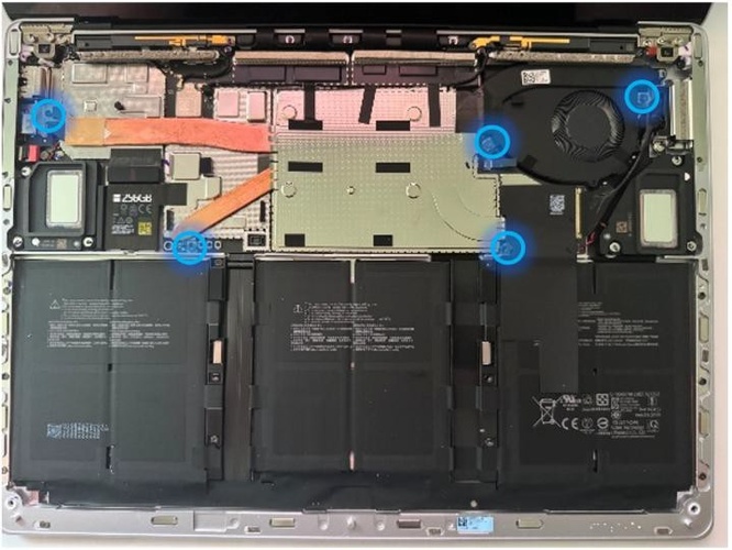
Remove Screws – Using a 3IP (Torx-plus) screwdriver, remove the four screws from under the four feet on the device.

Reverse Device – Turn device over so that top of device is facing up.

Open Device – Open screen to approximately 110-degrees.
Caution
Take care to prevent the keyboard power button from getting pressed during this step. If the power button is accidentally pressed and the device powers on, shut down the device as normal through the OS Start menu before continuing with repair.

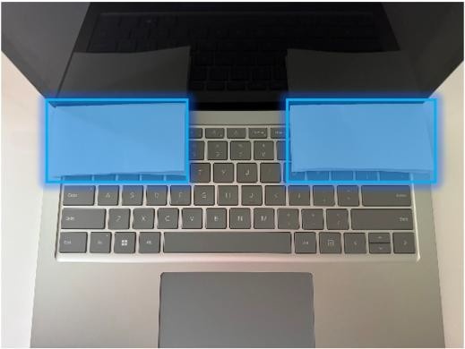
Separate keyboard from device – Grasp the back of the keyboard, by the Display and pull directly up. Keyboard should lift free from device.
Disconnect Keyboard – While holding the keyboard at a ~45-degree angle, use a Nylon Spudger to disconnect the keyboard connector from the motherboard.

Important
It's recommended to have a Surface Battery Cover (M1214771-001) placed across the device to protect the battery from any accidental damage during repair. Ensure the corners of the cover are always aligned with the corners of the device during repair. If the battery cover is misaligned during the repair, re- align before continuing repair activities.
Caution
When removed from the device, put the keyboard in a safe place with the key and trackpad side down and the connector facing up to avoid bending/creasing the connector’s cable. Be sure the key and trackpad side of the keyboard is protected from cosmetic damage by placing on a clean, soft surface.
Short jumper – Using metal tweezers, touch the two parts of the battery icon as shown for a few seconds. This shuts down the connection to the battery and prevent power-on during repair. The LED located next to it turns off if it was previously lit.

Remove TIM (Thermal Interface Material) from keyboard and rSSD – Using a plastic spudger, gently scrape away any remaining TIM from the bottom of the keyboard and rSSD. Any residue material should be removed using IPA and a cleaning swab.

Important
If you're only replacing the Keyboard Assembly, retain the TIM removed in Step 9 to be reapplied on the replacement Keyboard Assembly.
Important
Before completing the disassembly section, ensure all screws are accounted for and that no screws have been left in the disassembly area.
Procedure - Installation (Keyboard)
Important
Verify the condition of the Liquid Damage Indicator (LDI) inside the audio jack. Using a bright light, illuminate the interior of the audio jack port. If the indicator is any color other than white, then liquids have entered the device. In these scenarios, a whole unit replacement is necessary to ensure device functionality.
Replace TIM on Keyboard (only if reusing the same keyboard) – Place new TIM on Keyboard in the same position as previous TIM, and remove the protective film on the TIM.
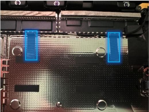
Apply Thermal Interface Material (TIM) to rSSD – Apply a thermal pad to the rSSD as shown in the image.

Remove tape from the new keyboard connector – Tape secures the keyboard connector during shipping. Remove this tape before continuing with assembling the device.
Connect Keyboard – While holding the keyboard at a 45-degree angle, use your hand to align the keyboard connector with the connector on the motherboard. Gently push the connector into place. Ensure the connector is attached completely with no gaps or looseness.
Caution
Ensure the keyboard connector’s ribbon cable doesn't get folded or creased during installation. Cable should sit in the device using the same bend with which it was shipped.
Protect the screw holes - to prevent stripping of the screw holes while fastening the Keyboard Assembly to the Enclosure in the next step, place 2 pieces of printer paper on the left and right hinge area in-between the Display and the Keyboard.
Align keyboard with chassis - Place the keyboard on top of chassis and press down on the Keyboard Assembly with both hands as indicated in the photo. Inspect all sides of the device and verify there are no discernable gaps between keyboard and the device enclosure when viewed from the side.

Caution
Before installing the keyboard, inspect the internal area for loose screws or debris, paying special attention to the magnetic areas around the chassis and the battery.
Close Display and invert device - with Display closed, turn over the device so that the bottom of the chassis is facing up.
Install new chassis screws – Using a 3IP (Torx-plus) screwdriver, install (1) new chassis screw
in each corner (4 total). Turn all
screws until snug and seated, and then turn another 45-degrees
(1/8th turn) to fully fasten.
Power on device – Carefully place device screen side up. Connect device to a power supply, open Display, and power on to the Windows desktop screen.
Run the Surface Diagnostic Toolkit (SDT) - Run SDT’s full diagnostic test to ensure device functions as expected.
Power down device – Power down device using the OS start menu. Once powered down, invert device so that the bottom chassis is facing up.
Install Feet – Refer to Procedure – Installation (Feet) for instructions on installing the feet on the device.
Thermal Module Replacement Process
Preliminary Requirements
Important
Be sure to follow all special (bolded) notes of caution within each process section.
- See Prerequisite Steps (All Repairs) section before beginning repair.
Required Tools
- Surface Battery Cover (M1214771-001)
- USB drive with SDT
- ESD-Safe Tweezers
- Metal Tweezers
- Anti-static wrist strap (1 MOhm resistance)
- Nylon Spudger/Probing Tool
- Isopropyl Alcohol (70% IPA)
- Cleaning Swabs
- 3IP (Torx-plus) Driver
- 5IP (Torx-plus) Driver
- Surface Power Supply
- Soft ESD-safe mat
- Microfiber Cloth
- Metal Tweezers
Primary Components
- Thermal Module (Refer to Illustrated Service Parts List)
- 1 x SOC Thermal Pad
- 1 x Shield Lid
- 1 x Antenna Cable Tape
- 1 x Conductive Tape Sponge
- 1 x Conductive Tape
- 1 x Lid Tape
- 1 x SSD Thermal Pad
- 1 x Mylar
5 x M1.2x3.3 3IP screws (Thermal Module)

P/N: 13N4-1EN0L01
2 x M1.2x2.3 3IP screws (Thermal Module)

P/N: 13N4-0FN1V21
4-6 x M1.2x1.7 3IP screws (Thermal Module)

P/N: 13N4-0FN2P12
2 x M1.2x2.0 3IP screws (Thermal Module: 13” only)

P/N: 13N4-1EN0X02
4 x M1.6x2.4 3IP Screws (Keyboard Assembly)
P/N: 13N4 – 0FN1V21
Additional Components (Ordered Separately)
- Feet (Refer to Illustrated Service Parts List)
Procedure - Removal (Thermal Module)
Position device - Place the device with bottom facing up.
Remove Feet – Refer to Procedure – Removal (Feet) for steps to remove the feet.
Remove Keyboard – Refer to Procedure – Removal (Keyboard) for steps to remove the keyboard.
Remove Conductive Tape – Pressing the thermal graphite sheet with your left hand, gently remove the Conductive Tape starting from the lower right.

Caution
If you're removing the Thermal Module for another repair and will be reusing, ensure no damage is present on the graphite sheeting after removal. If there's damage (bubbling, hole, tear, wrinkling, etc.) on the graphite sheet then the Thermal Module needs to be replaced.
Remove Graphite Sheet – Carefully lift and remove the black graphite sheet to expose the Motherboard.

Short jumper – Using metal tweezers, touch the two parts of the battery icon as shown for a few seconds. This shuts down the connection to the battery and prevent power-on during repair. The LED located next to it turns off if it was previously lit.
Remove Screws – this step differs slightly from the 13” and 15” models. See the marked sections for instructions for your device’s size.
- Screw Removal on 13” - Using a 3IP (Torx-plus) driver remove the 5 screws securing the Thermal Module + Fan to the chassis.
- Screw Removal on 15” – Using a 3IP (Torx-plus) driver remove the 6 screws securing the Thermal Module + Fan to the chassis.

Remove Antennae Cable tape – carefully remove the two pieces of black antennae tape from the thermal module.
Remove and reposition the right antenna – Using a Nylon spudger, remove the buckle of the right antenna. Place the antenna in the position shown in the second picture to avoid hitting the antenna connector.

Caution
Connectors on the Wi-Fi module are fragile. Don't attempt to remove with your fingers. If the connector is damaged, motherboard must be replaced. The nearby foams are also delicate – take care not to damage or remove them. DO NOT use metal tools for this process.

Remove Tape Sponge – Carefully remove the Tape Sponge from the thermal module.
Remove the Mylar (15” only) - Using ESD-Tweezers, gently peel off the mylar from the left to right.

Remove the fan connector – Using a Nylon Spudger, lift the locking tab on the fan connector and gently pull the fan cable out of the connector.

Caution
The fan connectors are delicate, so use extra care in the removal process. If the connector on the motherboard side is damaged, the motherboard will require replacement.
Remove the Lid Tape – Using the flat end of the Nylon Spudger, insert from the lower right corner of the Lid Tape, and lift to allow removal by hand.
Remove thermal module shield – Using ESD-safe Tweezers, work around the right-side of the thermal shield, gently prying it up. Once the right side is separated from the retention frame underneath the shield, gently pull up using fingers.

Remove socket screws – Using a 3IP (Torx-Plus) driver, remove the 4 socket screws securing the Thermal Module + Fan to the motherboard.

Remove thermal module – Using a Nylon Spudger, gently work under the edge of the thermal module to break the seal with the Thermal Interface Material (TIM) underneath. Gently lift out the thermal module, and place face down on a clean surface.
Clean residual Thermal Interface Material from PCBA – Using a Nylon Spudger gently scrape off left over TIM from the SOC. Use a cleaning swab soaked in Isopropyl Alcohol to completely remove any residual material from the board or any other surface to avoid damage to the Motherboard. Finally, allow the surface to dry completely before moving forward.

Clean residual Thermal Interface Material from Thermal Module (Part Re-use Only) – Using a Nylon Spudger gently scrape off left over TIM from the PCBA. Use a cleaning swab soaked in Isopropyl Alcohol to completely remove any residual material from the board. Finally, wipe the surface dry with a Microfiber cloth.
Apply new Thermal Interface Material to Thermal Module (Part Re-use Only) – Take 1 piece of new Thermal Interface Material and attach it to the bottom of the Thermal Module in the same place as the prior material was applied. Gently press on the Thermal Interface Material and remove the release paper.

Procedure - Installation (Thermal Module)
Install Thermal Module - Place new thermal module + fan into the device. Ensure the screw holes are aligned with the chassis points.
Important
Limit Thermal Module movement once the Thermal Module is placed in the device. Excessive movement may damage the Thermal Interface Material requiring replacement of the Thermal Interface Material.

Install socket screws - Using a 3IP (Torx-plus) drive, install the 4 new socket screws in each corner tensioner. Turn each screw until snug and seated. Once all screws are installed, turn each screw another 45 degrees (1/8 turn) to fully fasten.
Install Screws – this step differs slightly from the 13” and 15” models. See the marked sections for instructions for your device’s size.
- Screw Installation on 13” - Using a 3IP (Torx-plus) driver install the 5 screws securing the Thermal Module + Fan to the chassis.
- Screw Installation on 15” – Using a 3IP (Torx-plus) driver install the 6 screws securing the Thermal Module + Fan to the chassis.

Install thermal module shield - Align the shield around the retention frame and press down on the upper left corner. Work around the outer edge of the shield. As the shield seats properly, you should hear clicking.
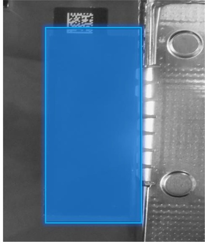
Apply Mylar Tape – Place new Mylar Tape so that it aligns with the edge of the bottom of the QR code as shown in the image. Press firmly to apply.
Apply Lid Tape - Place new Lid Tape so that it's aligned with the cover edge of the shield lid. Press firmly to apply.

Install fan connector - Reconnect the fan cable to the connector on the PCBA. Press the locking tab down to complete the connection.

Attach Rubber (15” model only) - Attach a new Rubber piece. Press firmly to apply.
Attach Tape Sponge - Attach a new Tape Sponge. Press firmly to apply.
Reposition and secure the right antenna – Reposition the black antennae cable and gently secure it, using the flat end of a Nylon Spudger or Finger, to the antennae connector on the motherboard.
Attach Antennae Cable Tape - Carefully place two pieces of antennae cable tape as shown in the photo. The Antennae cable must be placed over and above the sponge and can't be routed around it.
Install rSSD – Refer to Procedure – Installation (rSSD) for steps to install the rSSD.
Install Keyboard – Refer to Procedure – Installation (Keyboard) for steps to install the Keyboard.
Power on Device – Carefully reposition the device so that it's top side up. Connect the device to a power supply, open the Display, and power on to the Windows Desktop.
Run the Surface Diagnostic Toolkit (SDT) – Run all diagnostics to ensure the device is functioning as expected before moving forward.
Install Feet – Refer to Procedure – Installation (Feet) for steps to install Feet.
Storage (rSSD) Replacement Process
Preliminary Requirements
Important
Be sure to follow all special (bolded) notes of caution within each process section.
- See Prerequisite Steps (All Repairs) section before beginning repair.
Required Tools
- Surface Battery Cover (M1214771-001)
- USB Drive with SDT and BMR Image
- ESD-Safe Tweezers
- Anti-static wrist strap (1 MOhm resistance)
- Nylon Spudger/Probing Tool
- Isopropyl Alcohol (70% IPA)
- Cleaning Swabs
- 3IP (Torx-plus) Driver
- 5IP (Torx-plus) Driver
- Surface Power Supply
- Soft ESD-safe mat
- Microfiber Cloth
Primary Components
- rSSD (Refer to Illustrated Service Parts List)
1 x SSD Conductive Tape
1 x SSD Top Rubber
1 x SSD Thermal Pad
1 x SOC Thermal Pad
1 x Shield Lid
2 x Antenna Cable Tape
1 x Conductive Tape Sponge
1 x Conductive Tape
1 x Lid Tape
- 2 x M1.6x2.0 5 IP screws (rSSD)

- P/N: 13N4-1EN0L01
- 5 x M1.2x3.3 3IP screws (Thermal Module)
- 2 x M1.6x2.0 5 IP screws (rSSD)
P/N: 13N4-1EN0L01
2 x M1.2x2.3 3IP screws (Thermal Module)
P/N: 13N4-0FN1V21
4-6 x M1.2x1.7 3IP screws (Thermal Module)
P/N: 13N4-0FN2P12
2 x M1.2x2.0 3IP screws (Thermal Module: 13” only)
P/N: 13N4-1EN0X02
4 x M1.6x2.4 3IP Screws (Keyboard Assembly)
P/N: 13N4 – 0FN1V21
Additional Components (Ordered Separately)
- Feet (Refer to Illustrated Service Parts List)
Procedure - Removal (rSSD)
Remove Feet – Refer to Procedure – Removal (Feet) for steps to remove the feet.
Remove Keyboard – Refer to Procedure – Removal (Keyboard) for steps to remove the keyboard.
Remove Thermal Module – Refer to Procedure – Removal (Thermal Module) for steps to remove the Thermal Module.
Remove Thermal Interface Material (TIM) from rSSD – Use a Nylon spudger to gently scrape away any remaining TIM for the rSSD. Remaining residual can be removed with a cleaning swab soaked in Isopropyl Alcohol.
Remove SSD rubber and conductive tape from the top of the rSSD enclosure- using ESD-Safe tweezers, gently remove the rSSD rubber from the top of the rSSD. Next, remove the conductive tape from the top of the rSSD.

Remove rSSD screw – Using a 5IP (Torx-plus) driver, remove the screw securing the rSSD.

Remove rSSD – The rSSD should lift upwards to ~15-degrees after the screw is removed. Carefully grab the sides of the rSSD case and pull it out of the mainboard socket while maintaining the ~15- degree angle.
Procedure - Installation (rSSD)
Insert rSSD – Insert the connector end of the rSSD into the receptacle on the motherboard at a ~15- degree angle. Using a Nylon Spudger, push the drive into the receptacle to make clearance for the rSSD screw to be installed.

Install new rSSD screw – Using a 5IP (Torx-plus) screwdriver, install the rSSD screw. Turn the screw until snug and seated, and then turn another 45 degrees (1/8 turn) to fully fasten.
Install new SSD conductive tape and rubber around rSSD – Using ESD-Safe Tweezers, gently apply a new set of conductive tapes around the rSSD.
Apply Thermal Interface Material (TIM) – Apply a thermal pad to the rSSD as shown in the image.
Connect Keyboard – Connect keyboard as detailed in the Procedure – Installation (Keyboard) section, but don't install chassis screws before step 9 is completed.
Power on device – Carefully place the device with the screen side facing up. Connect the device to a power supply and open the Display.
Image the device – Reinstall the operating system and all drivers/firmware by using a USB-drive containing the latest Surface BMR for your model. See the Software Tools – Diagnostic, Calibration, and Troubleshooting section for links to instructions on how to get the latest image and install it.
Run the Surface Diagnostic Toolkit (SDT) – With Windows installed and sitting at the desktop, insert the USB drive containing SDT and launch the program. Run all diagnostics to ensure the device is functioning as expected before moving forward.
Install the Keyboard fully – Install the chassis screws to fully attach the keyboard to the chassis as detailed in the Procedure – Installation (Keyboard) section.
Install Feet – Refer to the Procedure – Installation (Feet) section for instructions.
Speaker Replacement Process
Preliminary Requirements
Important
Be sure to follow all special (bolded) notes of caution within each process section.
- See Prerequisite Steps (All Repairs) section before beginning repair.
Required Tools
- Surface Battery Cover (M1214771-001)
- ESD-Safe Tweezers
- USB drive with SDT
- Anti-static wrist strap (1 MOhm resistance)
- Nylon Spudger/Probing Tool
- Isopropyl Alcohol (70% IPA)
- Cleaning Swabs
- 3IP (Torx-plus) Driver
- 5IP (Torx-plus) Driver
- Surface Power Supply
- Soft ESD-safe mat
- Microfiber Cloth
Primary Components
- Speaker (Refer to Illustrated Service Parts List)
- 1 x Left Speaker
- 1 x Right Speaker
- 1 x Speaker Screw Rubber D
- 1 x Speaker Screw Rubber T
- 1 x SSD Thermal Pad
- 1 x SOC Thermal Pad
- 1 x Shield Lid
- 2 x Antenna Cable Tape
- 1 x Conductive Tape Sponge
- 1 x Conductive Tape
- 1 x Lid Tape
7 x M1.2x0.25 3IP screws (Speakers)

P/N: 13E5-2TN3V21
5 x M1.2x3.3 3IP screws (Thermal Module)
P/N: 13N4-1EN0L01
2 x M1.2x2.3 3IP screws (Thermal Module)
P/N: 13N4-0FN1V21
4-6 x M1.2x1.7 3IP screws (Thermal Module)
P/N: 13N4-0FN2P12
2 x M1.2x2.0 3IP screws (Thermal Module: 13” only)
P/N: 13N4-1EN0X02
4 x M1.6x2.4 3IP Screws (Keyboard Assembly)
P/N: 13N4 – 0FN1V21
Additional Components (Ordered Separately)
- Feet (Refer to Illustrated Service Parts List)
Procedure - Removal (Speakers)
Position device - Place the device with bottom facing up.
Remove Feet – Refer to Procedure – Removal (Feet) for steps to remove the feet.
Remove Keyboard – Refer to Procedure – Removal (Keyboard) for steps to remove the keyboard.
Remove Thermal Module – Refer to Procedure – Removal (Thermal Module) for steps to remove the Thermal Module.
Remove Speaker Screw Rubber- this step differs from the 13” and 15” models slightly. See the marked sections for instructions for your device’s size.
Speaker Rubber removal for 13” model – Using ESD-Safe Tweezers, remove the two Speaker Screw Rubbers from each speaker as shown in the photo.

Speaker Rubber removal for 15” model - Using ESD-Safe Tweezers, remove the singular Speaker Screw Rubbers from each speaker as shown in the photo.

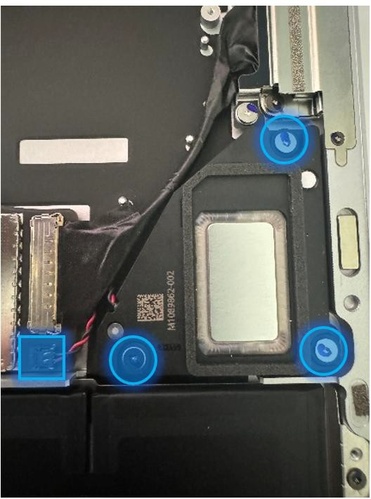
Remove the left speaker – Using a 3IP (Torx-plus) driver, remove the 3 screws securing the left speaker to the chassis. Disconnect the speaker from the motherboard using a Nylon Spudger, by carefully lifting the cable up from the motherboard. Remove the left speaker.
Caution
DO NOT attempt to pull the cable out. The cable slots into the connector from the top and should be gently lifted out of the chassis.

Remove the right speaker - Using a 3IP (Torx-plus) driver, remove the 3 screws securing the left speaker to the chassis. Disconnect the speaker from the motherboard using a Nylon Spudger, by lifting the cable up from the motherboard. Remove the right speaker.
Caution
DO NOT attempt to pull the cable out. The cable slots into the connector from the top and should be gently lifted out of the chassis.
Procedure - Installation (Speakers)
Install the left speaker – Place the left speaker in the chassis. Using a 3IP (Torx-plus) driver, install the 3 screws securing the left speaker to the chassis until finger tight. Then turn each screw an additional ~45 degrees (1/8 turn) to fully fasten. Gently connect the speaker cable to the motherboard using a Nylon Spudger or your finger.
Install audio cable (15” model only) – Locate the audio connector next to the left speaker and insert the cable connector into the connector on the Motherboard Module. Apply included protective film to the back of each connector. Press firmly with your hands to secure the connection.

Install the right speaker – Place the right speaker in the chassis. Using a 3IP (Torx-plus) driver, install the 3 screws securing the left speaker to the chassis until finger tight. Then turn each screw an additional ~45 degrees (1/8 turn) to fully fasten. Gently connect the speaker cable to the motherboard using a Nylon Spudger or your finger.
Install Keyboard – Refer to Procedure – Installation (Keyboard) for steps to install the keyboard.
Power on Device – Carefully reposition the device so that it's top side up. Connect the device to a power supply, open the Display, and power on to the Windows Desktop.
Run the Surface Diagnostic Toolkit (SDT) – Run all diagnostics to ensure the device is functioning as expected before moving forward.
Install Feet – Refer to Procedure – Installation (Feet) for steps to install Feet.
Display Assembly Replacement Process
Preliminary Requirements
Important
Be sure to follow all special (bolded) notes of caution within each process section.
Important
If replacing both the Motherboard Module and the Display Assembly – complete the Motherboard Module replacement prior to performing the Display Assembly Replacement to ensure proper part operation.
Required Tools
- Surface Battery Cover (M1214771-001)
- ESD-Safe Tweezers
- Metal Tweezers
- USB drive with SDT
- Anti-static wrist strap (1 MOhm resistance)
- Nylon Spudger/Probing Tool
- Isopropyl Alcohol (70% IPA)
- Cleaning Swabs
- 3IP (Torx-plus) Driver
- 6IP (Torx-plus) Driver
- Surface Power Supply
- Soft ESD-safe mat
- Microfiber Cloth
- 0.1mm thickness gauge
- 0.15mm thickness gauge
- Metal Tweezers
Primary Components
- Display Assembly (Refer to Illustrated Service Parts List)
- 1 x Hinge Rubber L
- 1 x Hinge Rubber R
- 1 x Shield Lid T1
- 1 x Shield Lid T2
- 1 x RF Lid Wall T1
- 1 x RF Lid Wall T2
- 2 x Antenna Cable Tape
- 1 x Conductive Tape Sponge
- 1 x SSD Thermal Pad
7 x M2.0x5.2 6IP screws (Display – Hinge screws)

P/N: 13N4-1EN0Y02
3 x M2.0x4.65 3IP screws (Display – Hinge TPU rubber screws)

P/N: 13N4-1EN0R01
4 x M1.6x2.4 3IP Screws (Keyboard Assembly)
P/N: 13N4 – 0FN1V21
Additional Components (Ordered Separately)
- Feet (Refer to Illustrated Service Parts List)
Procedure - Preparation (Display Assembly)
Important
This section is only for instances where you're replacing the Display. If the Display is being re- used, then this section is not required. If Display is unusable due to damage or fault, connect an external monitor to the device to perform these steps.
- Connect USB – Connect USB with the Surface Diagnostic Toolkit (SDT) loaded to an available USB port on the device under repair.
- Power on device – Connect a power supply to the device. Press the power button on the device to power the device on. Allow it to boot to the Windows Desktop before continuing.
- Launch SDT – From the Windows Desktop, use Windows Explorer to navigate to the USB drive. Select the SDT executable (.exe) to launch the Surface Diagnostic Toolkit.
- Run Touch Display Setup – From the SDT launch screen, select Repair from the drop-down menu. Next, select Repair Setup and Validation to enter the selection screen. Run the Touch Display (Setup) tool to prepare your device for Display replacement. Follow all on-screen instructions and allow the device to shut down when prompted. Disconnect the Power Supply and remove the USB drive before proceeding forward.
Procedure - Removal (Display Assembly)
Position device - Place the device with bottom facing up.
Remove Feet – Refer to Procedure – Removal (Feet) for steps to remove the feet.
Remove Keyboard – Refer to Procedure – Removal (Keyboard) for steps to remove the keyboard.
Short jumper – Using metal tweezers, touch the two parts of the battery icon as shown for a few seconds. This shuts down the connection to the battery and prevent power-on during repair. The LED located next to it turns off if it was previously lit.
Remove Hinge Rubber – Using ESD-Safe Tweezers, carefully remove the 3 pieces of rubber from around the hinges as identified in the photo (red boxes). Ensure you don't remove the 2 pieces of rubber near them (green arrows).

Remove Hinge TPU Rubber – Use a 3IP screwdriver to remove the 2 pieces of Hinge TPU Rubber from the device.

Remove the Tape Sponge – Using ESD-Safe Tweezers, carefully remove the tape sponge from the Thermal Module.

Remove the left and right RF Wall – Using a Nylon Spudger, remove the left and right RF Walls from the device.

Remove and reposition the right antenna – Using a Nylon spudger, remove the buckle of the right antenna. Place the antenna in the position show in the second picture to avoid hitting the antenna connector.
Caution
Connectors on the Wi-Fi module are fragile. Don't attempt to remove with your fingers. If the connector is damaged, motherboard must be replaced. The nearby foams are also delicate – take care not to damage or remove them. DO NOT use metal tools for this process.
Remove the antennae cable tape – Using ESD-Safe Tweezers, remove the 2 pieces of black antennae cable tape from the device.
Remove connector shielding - Using a pair of ESD-Safe Tweezers, remove the Display FPC shields. The right shield is pried up from the lower left corner, while the left shield is pried up from the lower right corner. Fold the shields up and remove them in parallel.
Caution
When removing the connector shields, ensure only to remove the black shields and not the silver shield retainers. The nearby foams are delicate. Take additional care not to damage or remove them.
Disconnect the Display connectors - Using a Nylon Spudger, remove the Display connectors one by one in the order detailed in the photo. Connectors in position 1, 2, 3 are disconnected from the lower right corner. The connector in the ##4 position is disconnected at a 90-degree angle from the lower left corner.

Remove the hinge screws - Holding the Display Assembly with one hand, use a 6IP (Torx-plus) driver, remove the 3 hinge screws on each hinge.

Remove the Display – Using two hands, lift the Display away from the chassis and set aside on a soft, clean surface free of debris that may damage the Display.

Clean rubber residue - Using a cleaning swab soaked in Isopropyl Alcohol, clean any residual rubber residue from the chassis where the hinges were previously attached.

Procedure - Installation (Display)

Position hinges - Place the backside of the replacement Display module on the ESD safe workbench. Adjust both hinges until they are approximately set to 90 degrees.
Install Display module onto chassis – While hosting the Display with both hands, carefully align the hinges so they fit into the pockets on each side of the chassis.

Pre-fasten the hinge screws – Using a 6IP (Torx-plus) drivers, assemble the 3 left and 3 right hinge screws in the order shown. Tighten each screw until snug.
Important
Ensure each screw can be inserted at a 90-degree angle. If any of the 6 hinge screws can't be inserted at 90-degrees, re-check hinge alignment with Enclosure before continuing.

Hinge alignment –
- Loosen all 6 hinge screws 90 degrees (1/4th turn).
- Carefully close Display.

- Using a 0.1mm plastic thickness gauge, verify the gauge can slide easily in the hinge gap.
- Open the lid and tighten 1 screw on each hinge until snug, then turn an additional 90 degrees (1/4th turn) and re-check alignment with the 0.1mm plastic thickness gauge.
- Repeat steps b through d on each of the 5 remaining hinge screws.
Install new hinge rubber – Using ESD-Safe Tweezers, place 3 pcs of rubber on the areas shown. There are different rubber pieces for 13” and 15” devices so ensure yours match the ones in the photo for your device.
a. 13” Devices:

Important
When installing the hinge rubber, ensure the protruding edge on the rubber piece is fitted into the narrow gap between the hinge and the device chassis.
b. 15” Devices:

Install new hinge TPU rubber – Using ESD-Safe Tweezers, place 1 piece of TPU rubber on both the left and right hinges. Use a 3IP (Torx-plus) driver to tighten a screw into each of the two TPU rubbers so that the screw head is not higher than the TPU surface.
Connect the Display cables - Carefully connect the 4 Display cables to the connectors on the PCBA. Perform a visual inspection to ensure all are fully connected before moving forward.
Install connector shielding – Using a pair of ESD-Tweezers, slide the Display cable shields into place. Once the shields are properly positioned, use your finger to press them into place.
Install the RF lid wall - place the 2 RF lid wall pieces on the connector shields as shown in the photo and press firmly to apply.
Important
The RF lids come in two design: T1 and T2. T1 is the shorter and T2 is the longer lid. For both lids, the side with holes should face away from the Display.

Install the tape sponge – Please a new tape sponge and press firmly with both hands to apply.
Install antenna – Using your fingers, gently move the black Wi-Fi antenna into place above the connector on the Wi-Fi module and press to apply with fingers or the flat end of a Nylon Spudger. The cable should route around and in front of the RF lid walls.

Caution
The connectors on the Wi-Fi module are fragile. If the connector is damaged, the Motherboard Module needs to be replaced.
Install the antenna cable tape - Apply 2 pieces of antenna cable tape to the locations outlined in the photo to secure the antenna cable to the thermal module shield.
Install Keyboard – Refer to Procedure – Installation (Keyboard) for steps to install the keyboard.
Power on Device – Carefully reposition the device so that it's top side up. Connect the device to a power supply, open the Display, and power on to the Windows Desktop.
Procedure - Finalize (Display Assembly)
Important
This section is only for instances where you're replacing the Display. If the Display is being re- used, then this section is not required. If Display is unusable due to damage or fault, connect an external monitor to the device to perform these steps.
Connect USB – Connect USB with the Surface Diagnostic Toolkit (SDT) loaded to an available USB port on the device under repair.
Launch SDT – From the Windows Desktop, use Windows Explorer to navigate to the USB drive. Select the SDT executable (.exe) to launch the Surface Diagnostic Toolkit.
Run Touch Display Calibration – From the SDT launch screen, select Repair from the drop-down menu. Next, select Repair Setup and Validation to enter the selection screen. Run the Touch Display (Calibration) tool to calibrate your new Display. Follow all on-screen instructions and allow the device to restart when prompted.
Important
If the calibration fails, reboot the device, and attempt again. If the failure continues, then the Display may be faulty and require replacement.
Launch SDT – Once the device has rebooted and is at the Windows Desktop, use Windows Explorer to navigate to the USB drive. Select the SDT executable (.exe) to launch the Surface Diagnostic Toolkit.
Run the Surface Diagnostic Toolkit (SDT) – Run all diagnostics to ensure the device is functioning as expected before moving forward.
Install Feet – Refer to Procedure – Installation (Feet) for steps to install Feet.
Surface Connect Replacement Process
Preliminary Requirements
Important
Be sure to follow all special (bolded) notes of caution within each process section.
Required Tools
- Surface Battery Cover (M1214771-001)
- ESD-Safe Tweezers
- Metal Tweezers
- USB drive with SDT
- Anti-static wrist strap (1 MOhm resistance)
- Nylon Spudger/Probing Tool
- Isopropyl Alcohol (70% IPA)
- Cleaning Swabs
- 3IP (Torx-plus) Driver
- Surface Power Supply
- Soft ESD-safe mat
- Microfiber Cloth
- Metal Tweezers
Primary Components
- Surface Connect (Refer to Illustrated Service Parts List)
- 1 x Surface Connect Cable
- 1 x SSD Thermal Pad
3 x M1.2x1.4 3IP screws (Surface Connect – Iron Plate)

P/N: 13N4-0FN1U12
3 x M1.2x2.2 3IP screws (Surface Connect – Iron Plate)

P/N: 13N4-1EN0J02
3 x M1.2x2.4 3IP screws (Surface Connect – SL Cable)

P/N: 13N4-0FN2K12
4 x M1.6x2.4 3IP screws (Keyboard Assembly)
P/N: 13N4 – 0FN1V21
Additional Components (Ordered Separately)
- Feet (Refer to Illustrated Service Parts List)
Procedure - Removal (Surface Connect)
Position device - Place the device with bottom facing up.
Remove Feet – Refer to Procedure – Removal (Feet) for steps to remove the feet.
Remove Keyboard – Refer to Procedure – Removal (Keyboard) for steps to remove the keyboard.
Short jumper – Using metal tweezers, touch the two parts of the battery icon as shown for a few seconds. This shuts down the connection to the battery and prevent power-on during repair. The LED located next to it turns off if it was previously lit.

Disconnect the Surflink connector from the Motherboard Module – Located the cooling fan, carefully pull back the thermal graphite to expose the Surflink cable on the motherboard. Lift the cable connector handle and delicately pull to the right to disengage the cable from the connector.

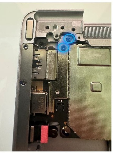
Remove bracket – Using a 3IP (Torx-plus) driver, remove the 4 bracket screws securing the bracket to the chassis. Remove the bracket.

Remove Surface Connect Screws – Using a 3IP (Torx-plus) driver, remove the 2 Surflink screws securing the Surface Connect to the chassis.

Remove Surface Connect – Remove the Surface Connect from the chassis.

Procedure - Installation (Surface Connect)
Install Surface Connect – Place the Surface Connect into the chassis. Ensure the chassis posts net into the Surface Connect slot.

Install new Surflink Screws – Using a 3IP (Torx-plus) driver, install 2 new Surflink screws. Turn all screws until snug and seated, and then turn each other 45-degress (1/8th turn) until fully fastened.
Reconnect the Surflink connector to the Motherboard Module – Located the cooling fan, carefully pull back the thermal graphite to expose the Surflink connector on the motherboard. Insert the Surflink cable into the connector on the motherboard and press down on the locking cover to fully secure the cable. Carefully reinstall the graphite sheet into its original position.
Install bracket – Place the Surflink bracket over the Surflink. Using a 3IP (Torx-plus) driver install 4 new Bracket Screws. Turn all screws until they are snug and seated, then turn each another 45-degrees (1/8th turn) or until fully fastened.
Install Keyboard – Refer to Procedure – Installation (Keyboard) for steps to install the keyboard.
Power on Device – Carefully reposition the device so that it's top side up. Connect the device to a power supply, open the Display, and power on to the Windows Desktop.
Launch SDT – Once the device has rebooted and is at the Windows Desktop, use Windows Explorer to navigate to the USB drive. Select the SDT executable (.exe) to launch the Surface Diagnostic Toolkit.
Run the Surface Diagnostic Toolkit (SDT) – Run all diagnostics to ensure the device is functioning as expected before moving forward.
Install Feet – Refer to Procedure – Installation (Feet) for steps to install the feet.
Motherboard Module Replacement Process
Preliminary Requirements
Important
Be sure to follow all special (bolded) notes of caution within each process section.
Important
If replacing both the Motherboard Module and the Display Assembly – complete the Motherboard Module replacement prior to performing the Display Assembly Replacement to ensure proper part operation.
Required Tools
- Surface Battery Cover (M1214771-001)
- ESD-Safe Tweezers
- USB drive with SDT
- Anti-static wrist strap (1 MOhm resistance)
- Nylon Spudger/Probing Tool
- Isopropyl Alcohol (70% IPA)
- Cleaning Swabs
- 3IP (Torx-plus) Driver
- 5IP (Torx-plus) Driver
- 6IP (Torx-plus) Driver
- Surface Power Supply
- Soft ESD-safe mat
- Microfiber Cloth
- Metal Tweezers
Primary Components
- Motherboard Module (Refer to Illustrated Service Parts List)
1 x PCB Screw Top
1 x Shield Lid T4
1 x Shield Lid T7
1 x rSSD Stiffener
1 x Hinge Rubber L
1 x Hinge Rubber R
1 x Shield Lid T1
1 x Shield Lid T2
1 x RF Lid T1
1 x RF Lid T2
1 x Foam Baffle
1 x Hinge Sticker
1 x USBA RF Foam
1 x SOC Thermal Pad
1 x Shield Lid T3
2 x Antenna Cable Tape
1 x Conductive Tape
1 x Conductive Tape Sponge
1 x T4 Lid Tape
1 x SSD Conductive Tape
1 x SSD Top Rubber
1 x SSD Thermal Pad
2 x M1.2x3.0 3IP screws (Left Antenna PCB)

P/N: 13N4-0FN3K02
2 x M1.6x2.3 3IP screws (Left Antenna PCB)

P/N: 13N4-1EN0E01
5 x M1.2x1.6 3IP screws (Left Antenna PCB)

P/N: 13N4-1EN0F02
2 x M1.6x2.0 5 IP screws (rSSD)
P/N: 13N4-1EN0L01
7 x M2.0x5.2 6IP screws (Display – Hinge screws)
P/N: 13N4-1EN0Y02
3 x M2.0x4.65 3IP screws (Display – Hinge TPU rubber screws)
P/N: 13N4-1EN0R01
7 x M1.2x1.4 3IP screws (Surface Connect – Iron Plate/Motherboard)

- P/N: 13N4-0FN1U12
4 x M1.2x2.2 3IP screws (Surface Connect – Iron Plate/Motherboard – Iron Piece)

P/N: 13N4-1EN0J02
3 x M1.2x2.4 3IP screws (Surface Connect – SL Cable)
P/N: 13N4-0FN2K12
4 x M1.2x0.25 3IP screws (Left Speaker)
P/N: 13E5-2TN3V21
5 x M1.2x3.3 3IP screws (Thermal Module)
P/N: 13N4-1EN0L01
4 x M1.2x2.3 3IP screws (Thermal Module/Motherboard – USB Bracket)

P/N: 13N4-0FN1V21
4-6 x M1.2x1.7 3IP screws (Thermal Module)
P/N: 13N4-0FN2P12
2 x M1.2x2.0 3IP screws (Thermal Module: 13” only)
P/N: 13N4-1EN0X02
4 x M1.6x2.4 3IP Screws (Keyboard Assembly)
P/N: 13N4 – 0FN1V21
Additional Components (Ordered Separately)
- Feet (Refer to Illustrated Service Parts List)
Procedure - Removal (Motherboard Module)
Position device - Place the device with bottom facing up.
Remove Feet – Refer to Procedure – Removal (Feet) for steps to remove the feet.
Remove Keyboard – Refer to Procedure – Removal (Keyboard) for steps to remove the keyboard.
Remove Thermal Module – Refer to Procedure – Removal (Thermal Module) for steps to remove the Thermal Module.
Remove Surface Connect - Refer to Procedure – Removal (Surface Connect) for steps to remove the Surface Connect.
Remove rSSD – Refer to Procedure – Removal (rSSD) for steps to remove the rSSD.
Remove Speakers – Refer to Procedure – Removal (Speakers) for steps to remove the Speakers.
Remove Display – Refer to Procedure – Removal (Display Assembly) for steps to remove the Display.
Remove Hinge Sticker - Position the device on its end so that the hinge recesses are facing up towards you. Remove the hinge sticker from between the hinge recesses.

Remove Foam – Locate the foam directly above the Wi-Fi module. Using ESD-Safe Tweezers, carefully remove the thin layer of foam.

Remove and reposition the right antenna – Using a Nylon spudger, unplug the buckle of the right antenna. Place the antenna in the position shown in the second picture to avoid hitting the antenna connector.

Remove Surface Connect connector from Motherboard - Carefully lift the thermal graphite sheet (no more than a 140 degree angle) and remove the Surface Connect connector from the Motherboard.
Remove the left antennae – Using a 3IP (Torx-plus) driver to remove the 6 screws on the left antennae located directly above the Wi-Fi module. Using a Nylon Spudger, disconnect the left antenna. Remove the antennae from the chassis.

Remove audio cable (15” model only) – Locate the audio cable next to the left speaker and lift the tape from the connector. Pulling back on the tape to remove the audio cable from the connector.

Remove the USB Bracket – Locate the USB bracket near the USB ports and follow the directions based on the model you're repairing as there are differences.
- Remove USB Bracket (13”) – Use a 3IP (Torx-plus) driver to remove the 2 screws securing the USB bracket to the chassis. Lift the bracket and remove from the device.
- Remove USB Bracket (15”) – Use a 3IP (Torx-plus) driver to remove the 3 screws securing the USB bracket to the chassis. Lift the bracket and remove from the device.

Remove the retention clip – Locate the metal retention clip directly above the USB ports. Using a 3IP (Torx-plus) driver, remove the 3 screws securing the retention clip to the chassis. Lift the retention clip and remove from the device.

Using ESD-Safe Tweezers, work your way around the two metallic shield lids until you can lift them from the device.

Remove Thermal Interface Material residue – Using the flat end of a Nylon Spudger, carefully remove any Thermal Interface Material from the chip under the larger left shield.

Remove Rubber Cap – Using a Nylon Spudger, carefully remove the rubber cap as identified in the photo.

Remove Fan Rubber (15” only) – Using ESD-Safe Tweezers, locate and remove the rubber block located near the fan.

Remove rSSD Stiffener – Using ESD-Safe Tweezers, locate and remove the rSSD Stiffener located directly next to the rSSD connector.

Remove Motherboard Shields – Using ESD-Safe Tweezers, remove the two metal shields identified in the image to expose the Motherboard screws.

Remove Motherboard Module screws – Using a 3IP (Torx-plus) driver, remove the 6 screws securing the Motherboard Module to the chassis. See the sections for exact locations as placement differs by device model.
- Remove Motherboard Module screws (13”) –
 b. Remove Motherboard Module screws (15”) –
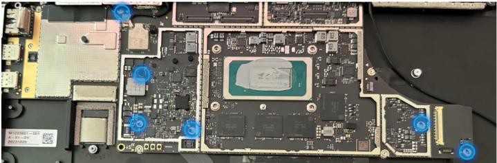
Remove Motherboard Module – Grab the right-hand side of the motherboard and lift until it's just off the chassis standoffs. Gently rotate the board towards you and pull gently to the right. A wiggling motion will be required to loosen the top of the board from the chassis. Once clear, lift the motherboard out of the chassis and place on an ESD-Safe mat.

Important
Don't remove the acetate cloth on the upper left lid of the Motherboard Module if re-using the Motherboard Module. It's also unnecessary in replacement scenarios as the new Motherboard Module will have the acetate cloth pre-applied.
Procedure - Installation (Motherboard Module)
Insert Motherboard Module – While holding the right-hand side of the motherboard, insert the USB ports into the left-hand side of the chassis. Once inserted, rotate the board down and into the chassis.

Install Motherboard Module screws – Using a 3IP (Torx-plus) driver, install the 6 screws securing the Motherboard Module to the chassis. See the sections for exact locations as placement differs by device model.
a) Install Motherboard Module screws (13”) –
b) Install Motherboard Module screws (15”) –
Install Rubber Cap – Using a Nylon Spudger, carefully apply the rubber cap as identified in the photo.
Install Shield Lids – Using ESD-Safe Tweezers, install the 2 Shield Lids to the Motherboard Module is the positions indicated.
Install Fan Rubber (15” only) – Using ESD-Safe Tweezers, locate and install the rubber block located near the fan.
Install the retention clip – Locate the metal retention clip directly above the USB ports. Using a 3IP (Torx-plus) driver, install the 3 screws securing the retention clip to the chassis.
Install the USB Bracket – Locate the USB ports and follow the directions based on the model you're repairing as there are differences.
- Install USB Bracket (13”) – Use a 3IP (Torx-plus) driver to install the 2 screws securing the USB bracket to the chassis.
- Install USB Bracket (15”) – Use a 3IP (Torx-plus) driver to install the 3 screws securing the USB bracket to the chassis.

Install the Surface Connect Connector to Motherboard – Carefully lift the graphite sheet and insert the Surface Connect Connector to the Motherboard.
Caution
If the graphite sheet is damaged in any way, the entire Thermal Module needs to be replaced.
Install audio cable (15” model only) – Locate the audio connector next to the right speaker. Take 1 piece of new Audio cable and insert an end into both the connector on the Motherboard and the connector on the Audio Board. Make sure the red line mark is aligned with the black connector with no gap. Using a pair of ESD-safe tweezers, remove the protective film on the back of the FPC and place an FPC on each connector. Press firmly with your hands to complete the application.

Install RF Foam – Locate the Shield Lid near the USB ports. In the upper left corner, install 1 piece of RF Foam as Displayed in the photo.

Install the left antennae – Using a 3IP (Torx-plus) driver, install the 6 screws on the left antennae located directly above the Wi-Fi module. Different screws are utilized for specific locations as identified in the image.
Install Foam – Locate the area directly above the Wi-Fi module as identified in the photo. Using ESD-Safe Tweezers, carefully apply the foam.
Connect the Antenna Buckle – Using your fingers or the flat end of a Nylon Spudger, reattach the left antenna cable to the Wi-Fi Module. Carefully apply pressure when aligned to establish the connection.

Install Speakers – Refer to Procedure – Installation (Speaker) for steps to install the Speakers.
Install Hinge Sticker – Position the device on its end so that the hinge recesses are facing up towards you. Install the hinge sticker between the hinge recesses. Press firmly with the flat end of a Nylon Spudger to secure. Remove the protective film and reapply pressure with the Nylon Spudger to ensure the sticker is secure.
Install Display – Refer to Procedure – Installation (Display Assembly) for steps to install the Display.
Install rSSD – Refer to Procedure – Installation (rSSD) for steps to install the rSSD.
Install Surface Connect – Refer to Procedure – Installation (Surface Connect) for steps to install the Surface Connect.
Install Thermal Module – Refer to Procedure – Installation (Thermal Module) for steps to install the Thermal Module.
Install Keyboard – Refer to Procedure – Installation (Keyboard) for steps to install the keyboard.
Procedure - Finalize (Motherboard Module)
Important
If replacing both the Motherboard Module and the Display Assembly – complete the Motherboard Module replacement prior to performing the Display Assembly Replacement to ensure proper part operation.
Power on Device – Connect a Power Supply to the device and power it on until it reaches the Windows Desktop.
Connect USB – Connect USB with the Surface Diagnostic Toolkit (SDT) loaded to an available USB port on the device under repair.
Launch SDT – From the Windows Desktop, use Windows Explorer to navigate to the USB drive. Select the SDT executable (.exe) to launch the Surface Diagnostic Toolkit.
Run Touch Display Calibration – From the SDT launch screen, select Repair from the drop-down menu. Next, select Repair Setup and Validation to enter the selection screen. Run the Touch Display (Calibration) tool to calibrate your new Display. Follow all on-screen instructions and allow the device to restart when prompted.
Important
If the calibration fails, reboot the device, and attempt again. If the failure continues, then the Display may be faulty and require replacement.
Allow the Battery to charge – With the device connected to a power supply, allow the battery to charge until the battery icon in Windows reads at least 50% remaining battery charge.
Launch SDT – Once the device has rebooted and is at the Windows Desktop, use Windows Explorer to navigate to the USB drive. Select the SDT executable (.exe) to launch the Surface Diagnostic Toolkit.
Run Battery Authentication – From the SDT launch screen, select Repair from the drop-down menu. Next, select Repair Setup and Validation to enter the selection screen. Select the Battery Repair (Validation) tool to ensure the battery is detected as properly authenticated. If the battery reads anything other than authenticated, run the Validation tool in its entirety.
Important
Battery authentication requires a stable internet connection and the latest version of the Surface Management Extension. If the battery validation tool fails or is not detected properly, install the Surface Management Extension, reboot the device, and try again with a new internet connection. If failures continue, reach out to Microsoft Support.
Run the Surface Diagnostic Toolkit (SDT) – Run all diagnostics to ensure the device is functioning as expected before moving forward.
Install Feet – Refer to Procedure – Installation (Feet) for steps to install Feet.
Audio Jack Replacement Process
Preliminary Requirements
Important
Be sure to follow all special (bolded) notes of caution within each process section.
Important
The removal process differs greatly between the 13” and 15” models. Please ensure you're looking at the correct section for the device you're servicing.
Required Tools
- Surface Battery Cover (M1214771-001)
- ESD-Safe Tweezers
- Metal Tweezers
- USB drive with SDT
- Anti-static wrist strap (1 MOhm resistance)
- Nylon Spudger/Probing Tool
- Isopropyl Alcohol (70% IPA)
- Cleaning Swabs
- 3IP (Torx-plus) Driver
- 5IP (Torx-plus) Driver
- 6IP (Torx-plus) Driver
- Surface Power Supply
- Soft ESD-safe mat
- Microfiber Cloth
- Headphones with 2.55mm connector
- Metal Tweezers
Primary Components
- Audio Jack (Refer to Illustrated Service Parts List)
1 x PCB Screw Top
1 x Shield Lid T4
1 x Shield Lid T7
1 x rSSD Stiffener
1 x Hinge Rubber L
1 x Hinge Rubber R
1 x Shield Lid T1
1 x Shield Lid T2
1 x RF Lid T1
1 x RF Lid T2
1 x Foam Baffle
1 x Hinge Sticker
1 x USBA RF Foam
1 x SOC Thermal Pad
1 x Shield Lid T3
2 x Antenna Cable Tape
1 x Conductive Tape
1 x Conductive Tape Sponge
1 x T4 Lid Tape
1 x SSD Conductive Tape
1 x SSD Top Rubber
1 x SSD Thermal Pad
2 x M1.2x3.0 3IP screws (Left Antenna PCB)
P/N: 13N4-0FN3K02
2 x M1.6x2.3 3IP screws (Left Antenna PCB)
P/N: 13N4-1EN0E01
5 x M1.2x1.6 3IP screws (Left Antenna PCB)
P/N: 13N4-1EN0F02
2 x M1.6x2.0 5 IP screws (rSSD)
P/N: 13N4-1EN0L01
7 x M2.0x5.2 6IP screws (Display – Hinge screws)
P/N: 13N4-1EN0Y02
3 x M2.0x4.65 3IP screws (Display – Hinge TPU rubber screws)
P/N: 13N4-1EN0R01
10 x M1.2x1.4 3IP screws (Surface Connect – Iron Plate/Motherboard)

- P/N: 13N4-0FN1U12
4 x M1.2x2.2 3IP screws (Surface Connect – Iron Plate/Motherboard – Iron Piece)
P/N: 13N4-1EN0J02
3 x M1.2x2.4 3IP screws (Surface Connect – SL Cable)
P/N: 13N4-0FN2K12
4 x M1.2x0.25 3IP screws (Left Speaker)
P/N: 13E5-2TN3V21
5 x M1.2x3.3 3IP screws (Thermal Module)
P/N: 13N4-1EN0L01
4 x M1.2x2.3 3IP screws (Thermal Module/Motherboard – USB Bracket)
P/N: 13N4-0FN1V21
6-8 x M1.2x1.7 3IP screws (Thermal Module)

P/N: 13N4-0FN2P12
2 x M1.2x2.0 3IP screws (Thermal Module: 13” only)
P/N: 13N4-1EN0X02
4 x M1.6x2.4 3IP Screws (Keyboard Assembly)
P/N: 13N4 – 0FN1V21
Additional Components (Ordered Separately)
- Feet (Refer to Illustrated Service Parts List)
Procedure – Removal (Audio Jack) 13” Model
Position device - Place the device with bottom facing up.
Remove Feet – Refer to Procedure – Removal (Feet) for steps to remove the feet.
Remove Keyboard – Refer to Procedure – Removal (Keyboard) for steps to remove the keyboard.
Remove Thermal Module – Refer to Procedure – Removal (Thermal Module) for steps to remove the Thermal Module.
Remove Surface Connect - Refer to Procedure – Removal (Surface Connect) for steps to remove the Surface Connect.
Remove rSSD – Refer to Procedure – Removal (rSSD) for steps to remove the rSSD.
Remove Speakers – Refer to Procedure – Removal (Speakers) for steps to remove the Speakers.
Remove Display – Refer to Procedure – Removal (Display Assembly) for steps to remove the Display.
Remove Motherboard Module – Refer to Procedure – Removal (Motherboard Module) for steps to remove the Motherboard Module.
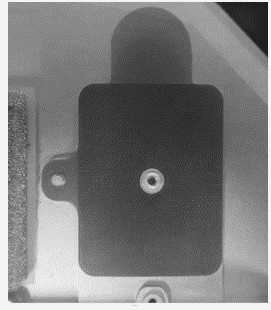
Remove Audio Jack – Using a 3IP (Torx-Plus) remove the audio screw. Lift the Audio Jack out of the chassis.

Procedure - Removal (Audio Jack) 15” Model
Position device - Place the device with bottom facing up.
Remove Feet – Refer to Procedure – Removal (Feet) for steps to remove the feet.
Remove Keyboard – Refer to Procedure – Removal (Keyboard) for steps to remove the keyboard.
Short jumper – Using metal tweezers, touch the two parts of the battery icon as shown for a few seconds. This shuts down the connection to the battery and prevent power-on during repair. The LED located next to it turns off if it was previously lit.
Remove audio cable– Locate the audio cable next to the left speaker and lift the tape from the connector. Pulling back on the tape to remove the audio cable from the connector.

Remove the Audio Board – Using a 3IP (Torx-plus) driver, remove the 2 audio board screws and the 1 Audio Jack screw. Once removed, lift the Audio Board out of the chassis.

Remove the Audio Jack – Lift the Audio Jack out of the chassis.
Procedure - Installation (Audio Jack) 13” Model
Install Audio Jack - Place Audio Jack into chassis, aligning the rear hole with the chassis riser to ensure part alignment.
Install Audio screw – Using a 3IP screwdriver, fasten the audio screw to the screw hole on the rear of the Audio Jack. Turn screw until snug, and then turn another 45-degress (1/8th) turn to fully fasten.
Install Motherboard Module – Refer to Procedure – Installation (Motherboard Module) for steps to install the Motherboard Module.
Install Speakers – Refer to Procedure – Installation (Speakers) for steps to install the Speakers.
Install Display – Refer to Procedure – Installation (Display Assembly) for steps to install the Display.
Install rSSD – Refer to Procedure – Installation (rSSD) for steps to install the rSSD.
Install Surface Connect – Refer to Procedure – Installation (Surface Connect) for steps to install the Surface Connect.
Install Thermal Module – Refer to Procedure – Installation (Thermal Module) for steps to install the Thermal Module.
Install Keyboard – Refer to Procedure – Installation (Keyboard) for steps to install the keyboard.
Connect USB – Connect USB with the Surface Diagnostic Toolkit (SDT) loaded to an available USB port on the device under repair.
Launch SDT – From the Windows Desktop, use Windows Explorer to navigate to the USB drive. Select the SDT executable (.exe) to launch the Surface Diagnostic Toolkit.
Run the Surface Diagnostic Toolkit (SDT) – Run all diagnostics to ensure the device is functioning as expected before moving forward.
Install Feet – Refer to Procedure – Installation (Feet) for steps to install Feet.
Procedure - Installation (Audio Jack) 15” Model
Install Audio Jack – Align the Audio Jack with the chassis riser so that the port is aligned with the exterior access. Use a 3IP (Torx-plus) driver to fasten the audio screw until snug. Turn an additional 45 degrees (1/8th turn) to fully secure.

Install the Audio Board – Insert the Audio Board over the Audio Jack. Using a 3IP (Torx-plus) driver to fasten the audio board screws (labeled 2 in the photo) until snug. Turn each screw an additional 45 degrees (1/8th turn) to fully secure.

Install a new Audio Cable – Take 1 new Audio cable and insert the connectors into the Motherboard Module and Audio board. Using ESD-Safe Tweezers, peel off the protective film on the back of each connector. Press firmly on each connector to ensure connection.

Install Keyboard – Refer to Procedure – Installation (Keyboard) for steps to install the keyboard.
Connect USB – Connect USB with the Surface Diagnostic Toolkit (SDT) loaded to an available USB port on the device under repair.
Launch SDT – From the Windows Desktop, use Windows Explorer to navigate to the USB drive. Select the SDT executable (.exe) to launch the Surface Diagnostic Toolkit.
Run the Surface Diagnostic Toolkit (SDT) – Run all diagnostics to ensure the device is functioning as expected before moving forward.
Install Feet – Refer to Procedure – Installation (Feet) for steps to install Feet.
Battery Replacement Process
Preliminary Requirements
Important
Be sure to follow all special (bolded) notes of caution within each process section.
Required Tools
- ESD-Safe Tweezers
- USB drive with SDT
- Anti-static wrist strap (1 MOhm resistance)
- Nylon Spudger/Probing Tool
- Isopropyl Alcohol (70% IPA)
- Cleaning Swabs
- 3IP (Torx-plus) Driver
- 5IP (Torx-plus) Driver
- 6IP (Torx-plus) Driver
- Surface Power Supply
- Soft ESD-safe mat
- Microfiber Cloth
- Bucket (4 gallons)
- Clean, dry, untreated sand (2.0 gallons)
Primary Components
- Battery (Refer to Illustrated Service Parts List)
1 x Battery FPC Conductive Tape
1 x Battery FPC PSA
1 x PCB Screw Top
1 x Shield Lid T4
1 x Shield Lid T7
1 x rSSD Stiffener
1 x Hinge Rubber L
1 x Hinge Rubber R
1 x Shield Lid T1
1 x Shield Lid T2
1 x RF Lid T1
1 x RF Lid T2
1 x Foam Baffle
1 x Hinge Sticker
1 x USBA RF Foam
1 x SOC Thermal Pad
1 x Shield Lid T3
2 x Antenna Cable Tape
1 x Conductive Tape
1 x Conductive Tape Sponge
1 x T4 Lid Tape
1 x SSD Conductive Tape
1 x SSD Top Rubber
1 x SSD Thermal Pad
13 – 16 M1.6x2.7 3IP screws (Battery)

P/N: 13N4-1EN0D01
2 x M1.2x3.0 3IP screws (Left Antenna PCB)
P/N: 13N4-0FN3K02
2 x M1.6x2.3 3IP screws (Left Antenna PCB)
P/N: 13N4-1EN0E01
5 x M1.2x1.6 3IP screws (Left Antenna PCB)
P/N: 13N4-1EN0F02
2 x M1.6x2.0 5 IP screws (rSSD)
P/N: 13N4-1EN0L01
7 x M2.0x5.2 6IP screws (Display – Hinge screws)
P/N: 13N4-1EN0Y02
3 x M2.0x4.65 3IP screws (Display – Hinge TPU rubber screws)
P/N: 13N4-1EN0R01
7 x M1.2x1.4 3IP screws (Surface Connect – Iron Plate/Motherboard)
- P/N: 13N4-0FN1U12
4 x M1.2x2.2 3IP screws (Surface Connect – Iron Plate/Motherboard – Iron Piece)
P/N: 13N4-1EN0J02
3 x M1.2x2.4 3IP screws (Surface Connect – SL Cable)
P/N: 13N4-0FN2K12
4 x M1.2x0.25 3IP screws (Left Speaker)
P/N: 13E5-2TN3V21
5 x M1.2x3.3 3IP screws (Thermal Module)
P/N: 13N4-1EN0L01
4 x M1.2x2.3 3IP screws (Thermal Module/Motherboard – USB Bracket)
P/N: 13N4-0FN1V21
4-6 x M1.2x1.7 3IP screws (Thermal Module)
P/N: 13N4-0FN2P12
2 x M1.2x2.0 3IP screws (Thermal Module: 13” only)
P/N: 13N4-1EN0X02
4 x M1.6x2.4 3IP Screws (Keyboard Assembly)
P/N: 13N4 – 0FN1V21
Additional Components (Ordered Separately)
- Feet (Refer to Illustrated Service Parts List)
Procedure - Preparation (Battery)
Important
This section is only for instances where you're replacing the battery. If the battery is being re- used, then this section is not required.
- Connect USB – Connect USB with the Surface Diagnostic Toolkit (SDT) loaded to an available USB port on the device under repair.
- Power on device – Connect a power supply to the device. Press the power button on the device to power the device on. Allow it to boot to the Windows Desktop before continuing.
- Launch SDT – From the Windows Desktop, use Windows Explorer to navigate to the USB drive. Select the SDT executable (.exe) to launch the Surface Diagnostic Toolkit.
- Run Battery Repair (Setup) – From the SDT launch screen, select Repair from the drop-down menu. Next, select Repair Setup and Validation to enter the selection screen. Run the Battery Repair (Setup) to put your device into repair mode. Follow all on-screen instructions and allow the device to shut down when prompted. Disconnect the Power Supply and remove the USB drive before proceeding forward.
Procedure - Removal (Battery)
- Position device - Place the device with bottom facing up.
- Remove Feet – Refer to Procedure – Removal (Feet) for steps to remove the feet.
- Remove Keyboard – Refer to Procedure – Removal (Keyboard) for steps to remove the keyboard.
- Remove Thermal Module – Refer to Procedure – Removal (Thermal Module) for steps to remove the Thermal Module.
- Remove Surface Connect - Refer to Procedure – Removal (Surface Connect) for steps to remove the Surface Connect.
- Remove rSSD – Refer to Procedure – Removal (rSSD) for steps to remove the rSSD.
- Remove Speakers – Refer to Procedure – Removal (Speakers) for steps to remove the Speakers.
- Remove Display – Refer to Procedure – Removal (Display Assembly) for steps to remove the Display.
- Remove Motherboard Module – Refer to Procedure – Removal (Motherboard Module) for steps to remove the Motherboard Module.
Important
Place the battery somewhere where the battery can't accidentally be contacted or damaged. DO NOT place anything on top of the battery.
Important
When disposing of the battery, ensure you're recycling according to local laws.
Important
The Motherboard Module and Battery are extremely sensitive to ESD and can be easily damaged It's critical that you ensure proper grounding before performing any work on these parts.
Warning
In the instance of a battery event, submerge the entire device in a 4-gallons bucket filled with 2 gallons of clean sand. Ensure the entire device is submerged. DO NOT attempt to pick up the device.
Remove Battery Screws – Using a 3IP (Torx-plus) driver, remove the battery screws according to the sections for the size of device you're servicing.
- Remove Battery Screws (13”) – Remove 12 screws from around the battery. See the photo for locations.

- Remove Battery Screws (15”) – Remove 15 screws from around the battery. See the photo for locations.

Remove Battery FPC – Using a Nylon Spudger, carefully lift the Battery FPC to disconnect it from the Enclosure. Lift from the device chassis.

Remove Battery – Carefully lift Battery from the device chassis. Place the battery on a clean ESD-Safe mat free of any items that may damage the battery in any way.
Remove the Battery FPC Contact Tape – Remove the Battery FPC Contact tape from where the Battery FPC previously was. Use a cleaning swab soaked in Isopropyl Alcohol to clean the area of any residual material.

Apply a new Battery FPC Contact Tape – Once the area has been cleaned and allowed to dry completely, apply 1 piece of new Battery FPC Contact Tape to the chassis according to the positioning hole. Remove the film covering the tape.
Inspect Battery FPC PSA (Battery Reuse) – If you're planning to re-use the same battery, inspect the Battery FPC PSA on the bottom of the Battery FPC. If it's damaged or has wrinkling, it needs to be removed. The area needs to be cleaned with a cleaning swab soaked in Isopropyl Alcohol and allowed to completely dry. Once dry, place 1 piece of new Battery FPC PSA to the Battery FPC so that the holes align, and no wrinkles or deformations are present.

Procedure - Installation (Battery)
Install Battery – Holding the Battery with both hands, place the battery into the device chassis so that it aligns with the positioning pins on the chassis.

Install Battery FPC – Remove the liner on the Battery FPC and attach it to the chassis in accordance with the positioning holes.
Install Battery Screws – Using a 3IP (Torx-plus) driver, install the battery screws according to the sections for the size of device you're servicing.
- Install Battery Screws (13”) – Install 12 screws around the battery. See the photo for locations.
- Install Battery Screws (15”) – Install 15 screws around the battery. See the photo for locations.
Install Motherboard Module – Refer to Procedure – Installation (Motherboard Module) for steps to install the Motherboard Module.
Install Speakers – Refer to Procedure – Installation (Speakers) for steps to install the Speakers.
Install Display – Refer to Procedure – Installation (Display Assembly) for steps to install the Display.
Install rSSD – Refer to Procedure – Installation (rSSD) for steps to install the rSSD.
Install Surface Connect – Refer to Procedure – Installation (Surface Connect) for steps to install the Surface Connect.
Install Thermal Module – Refer to Procedure – Installation (Thermal Module) for steps to install the Thermal Module.
Install Keyboard – Refer to Procedure – Installation (Keyboard) for steps to install the keyboard.
Procedure - Finalize (Battery)
Power on Device – Connect a Power Supply to the device and power it on until it reaches the Windows Desktop.
Connect USB – Connect USB with the Surface Diagnostic Toolkit (SDT) loaded to an available USB port on the device under repair.
Launch SDT – From the Windows Desktop, use Windows Explorer to navigate to the USB drive. Select the SDT executable (.exe) to launch the Surface Diagnostic Toolkit.
Allow the Battery to charge – With the device connected to a power supply, allow the battery to charge until the battery icon in Windows reads at least 50% remaining battery charge.
Run Battery Authentication – From the SDT launch screen, select Repair from the drop-down menu. Next, select Repair Setup and Validation to enter the selection screen. Select the Battery Repair (Validation) tool and follow the on-screen prompts until a successful authentication is completed.
Important
Battery authentication requires a stable internet connection and the latest version of the Surface Management Extension. If the battery validation tool fails or is not detected properly, install the Surface Management Extension, reboot the device, and try again with a new internet connection. If failures continue, reach out to Microsoft Support.
Run the Surface Diagnostic Toolkit (SDT) – Run all diagnostics to ensure the device is functioning as expected before moving forward.
Install Feet – Refer to Procedure- Installation (Feet) for steps to install Feet.
Enclosure Replacement Process
Preliminary Requirements
Important
Be sure to follow all special (bolded) notes of caution within each process section.
Important
The serial number for this device is located on its original chassis. To keep track of the device’s serial number, please record it using waterproof ink, on a sticker or label, and apply the sticker or label to an easily accessible area on the device’s exterior. The serial number can't be added permanently to a replacement part. Microsoft may have provided a label for this use in the replacement part’s packaging.
Required Tools
- ESD-Safe Tweezers
- USB drive with SDT
- Anti-static wrist strap (1 MOhm resistance)
- Nylon Spudger/Probing Tool
- Isopropyl Alcohol (70% IPA)
- Cleaning Swabs
- 3IP (Torx-plus) Driver
- 5IP (Torx-plus) Driver
- 6IP (Torx-plus) Driver
- Surface Power Supply
- Soft ESD-safe mat
- Microfiber Cloth
- Bucket (4 gallons)
- Clean, dry, untreated sand (2.0 gallons)
Primary Components
- Enclosure (Refer to Illustrated Service Parts List)
1 x Battery FPC Conductive Tape
1 x Battery FPC PSA
1 x PCB Screw Top
1 x Shield Lid T4
1 x Shield Lid T7
1 x rSSD Stiffener
1 x Hinge Rubber L
1 x Hinge Rubber R
1 x Shield Lid T1
1 x Shield Lid T2
1 x RF Lid T1
1 x RF Lid T2
1 x Foam Baffle
1 x Hinge Sticker
1 x USBA RF Foam
1 x SOC Thermal Pad
1 x Shield Lid T3
2 x Antenna Cable Tape
1 x Conductive Tape
1 x Conductive Tape Sponge
1 x T4 Lid Tape
1 x SSD Conductive Tape
1 x SSD Top Rubber
1 x SSD Thermal Pad
13 – 16 M1.6x2.7 3IP screws (Battery)
P/N: 13N4-1EN0D01
2 x M1.2x3.0 3IP screws (Left Antenna PCB)
- P/N: 13N4-0FN3K02
2 x M1.6x2.3 3IP screws (Left Antenna PCB)
P/N: 13N4-1EN0E01
5 x M1.2x1.6 3IP screws (Left Antenna PCB)
P/N: 13N4-1EN0F02
2 x M1.6x2.0 5 IP screws (rSSD)
P/N: 13N4-1EN0L01
7 x M2.0x5.2 6IP screws (Display – Hinge screws)
P/N: 13N4-1EN0Y02
3 x M2.0x4.65 3IP screws (Display – Hinge TPU rubber screws)
P/N: 13N4-1EN0R01
10 x M1.2x1.4 3IP screws (Surface Connect – Iron Plate/Motherboard)
- P/N: 13N4-0FN1U12
4 x M1.2x2.2 3IP screws (Surface Connect – Iron Plate/Motherboard – Iron Piece)
P/N: 13N4-1EN0J02
3 x M1.2x2.4 3IP screws (Surface Connect – SL Cable)
P/N: 13N4-0FN2K12
4 x M1.2x0.25 3IP screws (Left Speaker)
P/N: 13E5-2TN3V21
5 x M1.2x3.3 3IP screws (Thermal Module)
P/N: 13N4-1EN0L01
4 x M1.2x2.3 3IP screws (Thermal Module/Motherboard – USB Bracket)
P/N: 13N4-0FN1V21
6-8 x M1.2x1.7 3IP screws (Thermal Module)
P/N: 13N4-0FN2P12
2 x M1.2x2.0 3IP screws (Thermal Module: 13” only)
P/N: 13N4-1EN0X02
4 x M1.6x2.4 3IP Screws (Keyboard Assembly)
P/N: 13N4 – 0FN1V21
Additional Components (Ordered Separately)
- Feet (Refer to Illustrated Service Parts List)
Procedure - Removal (Enclosure)
- Position device - Place the device with bottom facing up.
- Remove Feet – Refer to Procedure – Removal (Feet) for steps to remove the feet.
- Remove Keyboard – Refer to Procedure – Removal (Keyboard) for steps to remove the keyboard.
- Remove Thermal Module – Refer to Procedure – Removal (Thermal Module) for steps to remove the Thermal Module.
- Remove Surface Connect - Refer to Procedure – Removal (Surface Connect) for steps to remove the Surface Connect.
- Remove rSSD – Refer to Procedure – Removal (rSSD) for steps to remove the rSSD.
- Remove Speakers – Refer to Procedure – Removal (Speakers) for steps to remove the Speakers.
- Remove Display – Refer to Procedure – Removal (Display Assembly) for steps to remove the Display.
- Remove Motherboard Module – Refer to Procedure – Removal (Motherboard Module) for steps to remove the Motherboard Module.
- Remove Audio Jack – Refer to Procedure – Removal (Audio Jack) for steps to remove the Audio Jack.
- Remove Battery – Refer to Procedure – Removal (Battery) for steps to remove the Battery.
Procedure - Removal (Enclosure)
Inspect Battery FPC PSA (Battery Reuse) – If you're planning to re-use the same battery, inspect the Battery FPC PSA on the bottom of the Battery FPC. If it's damaged or has wrinkling, it needs to be removed. The area needs to be cleaned with a cleaning swab soaked in Isopropyl Alcohol and allowed to completely dry. Once dry, place 1 piece of new Battery FPC PSA to the Battery FPC so that the holes align, and no wrinkles or deformations are present.
Install Battery – Refer to Procedure – Installation (Battery) for steps to install the Battery.
Install Audio Jack – Refer to Procedure – Installation (Audio Jack) for steps to install the Audio Jack.
Install Motherboard Module – Refer to Procedure – Installation (Motherboard Module) for steps to install the Motherboard Module.
Install Speakers – Refer to Procedure – Installation (Speakers) for steps to install the Speakers.
Install Surface Connect – Refer to Procedure – Installation (Surface Connect) for steps to install the Surface Connect.
Install rSSD – Refer to Procedure – Installation (rSSD) for steps to install the rSSD.
Install Thermal Module – Refer to Procedure - Installation (Thermal Module) for steps to install the Thermal Module.
Install Lid Top Rubber (15” Model Only) - Apply 1 piece of Lid Top Rubber to the Right Speaker as indicated in the image.


Install Right Speaker Rubber – Apply 1 piece of Speaker Rubber to the Right Speaker as indicated in the image.
Install Display – Refer to Procedure – Installation (Display Assembly) for steps to install the Display.
Install Keyboard – Refer to Procedure – Installation (Keyboard) for steps to install the keyboard.
Power on Device – Connect a Power Supply to the device and power it on until it reaches the Windows Desktop.
Connect USB – Connect USB with the Surface Diagnostic Toolkit (SDT) loaded to an available USB port on the device under repair.
Launch SDT – From the Windows Desktop, use Windows Explorer to navigate to the USB drive. Select the SDT executable (.exe) to launch the Surface Diagnostic Toolkit.
Run the Surface Diagnostic Toolkit (SDT) – Run all diagnostics to ensure the device is functioning as expected before moving forward.
Install Feet – Refer to Procedure – Installation (Feet) for steps to install Feet.