Note
Access to this page requires authorization. You can try signing in or changing directories.
Access to this page requires authorization. You can try changing directories.
Warning
Review the General Safety Precautions and Battery Safety guidelines in their entirety before proceeding with any repair steps.
Important
Read this Guide in its entirety before starting any repairs. If at any point you're unsure or uncomfortable about performing the repairs, as detailed in this Guide, DO NOT proceed. Contact Microsoft for more support options.
Warning
Failure to follow the instructions in this Guide, use of non-Microsoft (nongenuine), incompatible, or modified replacement parts, and/or failure to use proper tools could result in serious injury, death, and/or damage to the product or other property.
Prerequisite Steps
Steps outlined in this section should be conducted prior to starting any repair on a Surface device.
Power off device – Ensure the device is powered off completely and the battery has been fully discharged. Refer to the Repair-specific precautions and warnings for guidelines. Once discharged, the device should be disconnected from all power sources.
ESD Prevention – Ensure ESD prevention steps and general guidelines are followed prior to opening the device. Refer to the ESD Prevention section for guidelines.
Position Device – To prevent damage to the device, ensure the device is placed on a clean surface free of debris.
Non-Skid Feet Replacement Process
Preliminary Requirements
Important
Be sure to follow all special (bolded) notes of caution within each process section.
Required Tools and Components
- Tools:
- Plastic tweezers / spudger
- Isopropyl Alcohol Dispenser Bottle (use only 70% IPA)
- Cleaning swabs
- Components:
- Feet (Refer to Illustrated Service Parts List)
- Front Foot
- Rear Foot
Prerequisite Steps:
- Power off device – Ensure device is powered off and disconnected from a power supply.
- General Safety – Check to make sure that general guidelines and ESD compliance steps are followed prior to opening the device.
- Position device – To prevent scratches, flip device over onto a clean surface free of debris with the device bottom facing up for access to the feet for removal.
Procedure – Removal (Non-Skid Feet)
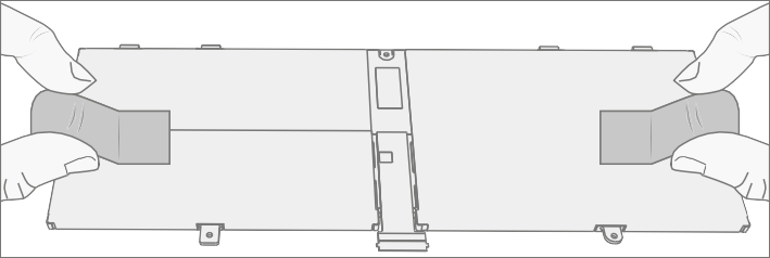
Remove Feet – Use a plastic tool to pry up the foot from one end and then peel to remove. Repeat for the other foot.
Important
The front and back feet aren't the same. There's one locating post on the rear foot near the left hinge and two locating posts for the front foot below the trackpad – refer to illustration for details.
Feet removal technique – Use plastic tweezers / spudger to lift one edge of each foot. Grasp the loose end and pull the foot from the D-Bucket. Ensure all adhesive tape remnants and glue residue are removed. Clean the D-Bucket foot recesses with 70% Isopropyl Alcohol.
Important
Once removed, the Feet will be stretched out of shape and must be replaced with new ones.
Procedure – Installation (Non-Skid Feet)
Important
Any further repairs that are required on the device should be carried out prior to feet installation. Don't reuse feet previously removed from a device.
Prepare new front foot and press into place – To install the front foot, remove protective sheet to expose adhesive on foot. Align the two locating posts for the front foot. Press the foot in firmly. Then slide your hand up and down the length of the foot to ensure that it's secured in place.
Inspect for anomalies – Examine foot to ensure no cosmetic damage or gaps between the foot and the D-Bucket foot recesses exist.
Prepare new back foot and press into place – To install the back foot, remove protective sheet to expose adhesive on foot. Align the one locating post for the back foot. Press the foot in firmly. Then slide your hand up and down the length of the foot to ensure that it's secured in place.
Inspect for anomalies – Inspect foot to ensure no cosmetic damage or gaps between the foot and the D-Bucket foot recesses exist.
Important
Before transporting the device, we recommend letting it sit feet-down on a tabletop for at least 12 hours. If this isn’t possible, it’s recommended to avoid placing the device in a backpack, purse, other types of carriers, until at least 12 hours after installing new feet.
C-Cover Keyboard Assembly Replacement Processes
Preliminary Requirements
Important
Be sure to follow all special (bolded) notes of caution within each process section.
Required Tools and Components
- Tools:
- Software Tool – SDT
- Plastic tweezers
- Plastic Opening Picks
- Plastic Opening tool
- Isopropyl Alcohol Dispenser (use only 70% IPA)
- PH0 Screwdriver
- Anti-static wrist strap (1M Ohm resistance)
- ESD-safe Surface Battery Cover (M1214771-001)
- Components:
- C-Cover (if replacing refer to Illustrated Service Parts List) MS20055I430 M2x5.5 Screws qty=2 (Supplied with C-Cover) MM20048I000 M2x4.8 Screws qty=5 (Supplied with C-Cover)
- Feet (Refer to Illustrated Service Parts List)
Important
There are C-Covers with and without a fingerprint reader. Ensure the new C-Cover used matches the original. The fingerprint reader is integrated into the power button. Without the fingerprint reader, a physical bump is present on the upper right-hand corner.

Prerequisite Steps:
- Power off device – Ensure device is powered off and disconnected from a power supply.
- General Safety – Check to make sure that general guidelines and ESD compliance steps are followed prior to opening device.
- Remove feet – Follow steps for Procedure – Removal (Non-Skid Feet).
Procedure Removal C-Cover Keyboard
Remove C-Cover screws – Using a PH0 screwdriver uninstall the three screws from the rear, and four screws from the front D-Bucket foot recesses.


Caution
Ensure the plastic pick depth into the C-Cover is kept shallow to avoid damaging snaps and impacting the battery.
Caution
Remove C-Cover exactly as described in this step to avoid damaging the Flexible Printed Circuit (FPC) connected between the C-Cover and the Main Board. Don't pull the C-Cover apart beyond 45 degrees otherwise damage to C-Cover FPC could occur.
Separate C-Cover from device
Note the locations of the snaps that secure the C-Cover to the D-Bucket.

Open the device to 90 degrees and place the display side down with the keyboard facing up.

Using a plastic opening tool to pry between the C-Cover and D-Bucket along the front between the snap locations. Rotate the opening tool by about 15 degrees and slowly run the tool along the seam between the C-Cover and D-Bucket. Start along the front seam and then the two sides until all snaps of C-Cover are disengaged.

Gently rotate the opening tool at the hinge corner until you hear a soft pop from the snap. Repeat this for both hinges.


To disengage the four vent snaps, ensure the device is open to 90 degrees and the display is lying flat on the work surface. Gently push the C-Cover downward towards the work surface and rotate it for towards the screen.

Disconnect FPCs – With the C-Cover rotated towards the screen, lift the connector lock on the battery FPC and then pull out the FPC. Next lift the connector lock on the keyboard FPC and then pull out the FPC.

Warning
It's recommended that an ESD-safe battery cover be placed across the device to protect the battery from any physical contact or accidental damage whenever C-Cover is removed. Ensure corners of cover are always aligned with the corners of the device while battery is exposed. If battery cover is misaligned during activities in any way, realign before continuing activities.
Caution
When removed from the device, place the C-Cover in a safe place with key and trackpad side down and FPC facing up to avoid bending/creasing the FPC. Be sure the key and trackpad side of the C-Cover is protected from cosmetic damage during storage.
Important
Ensure battery FPC remains disconnected from the PCBA whenever C-Cover is removed from device for safety purposes.
Procedure – Installation (C-Cover Keyboard)
Preinstallation Device Inspection
Warning
Verify the battery’s condition refer to the M1153910 In Device Battery Inspection process. Devices exhibiting battery issues as outlined in the Battery Inspection Process require whole unit replacement.
Warning
Verify the condition of LDI (Liquid Damage Indicators). Any color other than white indicates liquids have entered the device. Devices exhibiting LDI require whole unit replacement.
Check for unexpected items within device – Check C-Cover (both sides) and device enclosure for any loose articles that may be present inadvertently on the C-Cover or within the device enclosure areas.
Check and remove any foreign objects that the magnets may have attracted or that may have been accidentally introduced into the device during replacement.

D-Bucket

C-Cover
Carefully inspect the area around battery specifically for any foreign objects before removing battery cover.
Check C-Cover / D-Bucket Snaps – Verify the 16 C-Cover snaps and the four D-Bucket snaps weren't damaged during device disassembly. Damaged C-Cover snaps require installing a new C-Cover. Damaged D-Bucket snaps can only be addressed by whole device replacement. Refer to illustrations for further details.

Remove tape from new C cover FPC – Tape secures the C-Cover FPC during shipping. Remove this tape before continuing with assembly.
Connect C-Cover FPC – Remove the battery cover. Hover the C-Cover over the device while assembling the C-Cover FPC to the main board. Slide the FPC into the connector and then press down on the locking tab.

Caution
Be sure that FPC bends fall in place properly as prebent and no folds or creases are created during reassembly of C-Cover.
Connect Battery FPC – Connect the Battery FPC to the Motherboard. Slide the FPC into the connector and then press down on the locking tab.

Align the C-Cover – Properly align the cover to the device using the front edge alignment posts. Carefully place the C-Cover back onto the D-Bucket and shift the C-Cover snaps into place. Press gently on the C-Cover to engage the snaps correctly. Follow the direction of progress as shown in the picture below. Verify there are no visible gaps between the C-Cover and D-Bucket.

Caution
Ensure that the C-Cover is correctly aligned and seated before closing the device. There's the risk of breaking the display if the device lid is closed before C-Cover is aligned.
Run SDT to ensure all device features and functions operate as expected. Refer to Surface Diagnostic Toolkit - User Guide for details on SDT.
Install New C-Cover Screws – Close the AB-Cover and turn the unit over. Use a PH0 screwdriver to install seven new screws to secure the C-Cover in the order pictured below. There are five MM20048I000 screws and two MS20055I430 screws. They should be installed until snug and seated, and then turned another 90 degrees (1/4 turn).

Caution
Ensure the longer MS20055I430 screws are installed in the two corner locations under the rear foot pad.
Install Feet – If SDT tests pass and no further repairs are to be performed on the device, follow steps for Procedure – Installation (Non-Skid Feet) on Procedure – Installation (Non-Skid Feet).
Procedure – Finalize Installation for Substitute C-Cover Keyboard
Important
If a "substitute" C-cover Keyboard SKU is being installed (Refer to Service Parts List for details), you'll need to install a new firmware to your device to enable functionality of the fingerprint reader.
Follow the instructions below to perform the firmware installation needed for substitute C-cover Keyboard.
- On a separate device, download the file called "SurfaceLaptopGo2_FingerprintDriver.zip" from the Download center.
- Unzip the file and transfer the unzipped folder onto a USB thumb drive.
- Turn on your Surface Laptop Go 2 device, insert the thumb drive and navigate to the Device Manager.
- Locate the fingerprint reader device (shown as an unrecognized device) and right click on the device.
- Select "update driver" and proceed to install the driver manually by selecting "Browse" and navigating to where the thumb drive is located. Select the driver folder and install.
rSSD Replacement Process
Preliminary Requirements
Important
Be sure to follow all special (bolded) notes of caution within each process section.
Required Tools and Components
- Tools:
- USB Thumb drive with SDT
- Plastic tweezers
- Plastic Opening Picks iFixit Opening Picks
- Plastic Opening tool iFixit Plastic Opening Tool
- Isopropyl Alcohol Dispenser (use only 70% IPA)
- PH0 Screwdriver
- PH00 Screwdriver
- Anti-static wrist strap (1M Ohm resistance)
- ESD-safe Surface Battery Cover (M1214771-001)
- Components:
- rSSD (Refer to Illustrated Service Parts List) SSD Shielding cover (Supplied with rSSD)
- MS20055I430 M2x5.5 Screws qty=2 (Supplied with rSSD)
- MM20048I000 M2x4.8 Screws qty=5 (Supplied with rSSD)
- MM16030I130 M1.6x3 Screws qty=1 (Supplied with rSSD)
- Feet (Refer to Illustrated Service Parts List)
Prerequisite Steps:
- Power off device – Ensure device is powered off and disconnected from a power supply.
- General Safety – Check to make sure that general guidelines and ESD compliance steps are followed prior to opening device.
- Remove feet – Follow steps for Procedure – Removal (Non-Skid Feet).
- Remove C-Cover – Follow steps for Procedure Removal C-Cover Keyboard
Procedure Removal rSSD
Remove SSD Shielding cover and Screw – Use a plastic opening tool to pry up Shielding cover. Slide the tool under the lip on the top side of the shield. Use a PH00 screwdriver to remove the screw securing the rSSD.

Clean TIM Residue – Inspect rSSD for TIM residue. Carefully wipe away any residue with 70% IPA solution.
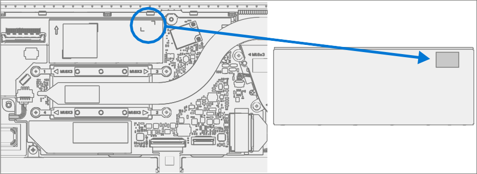
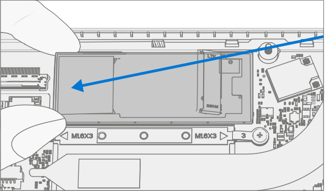
Remove SSD – Carefully grab sides of rSSD case and pull out of the mainboard socket at ~15-degree angle.

Procedure Installation rSSD
Important
Only a Microsoft rSSD with part number as specified in the parts list, per device model, and of like capacity should be replaced in the device.
Insert rSSD – Insert the connector end of the rSSD into the SSD connector on Mainboard at ~15-degree angle.

Install new rSSD screw – Using a PH00 screwdriver install a new MM16030I130 rSSD screw until the screw is snug and seated, and then turned another 45 degrees (1/8 turn).

Install SSD Shielding cover – Install a new Shielding cover on Main board.
Install C-Cover – Follow steps for Procedure – Installation (C-Cover Keyboard).
Note
Only snap the C-Cover in place.
Imaging new rSSD – Power on device. Apply a new image to the rSSD using a BMR Imaging key specific to the device model. Refer to Surface imaging process - Surface Imaging Tools Link
Run SDT – Run SDT to ensure all device features and functions operate as expected. Refer to Surface Diagnostic Toolkit - User Guide for details on SDT. If SDT tests pass and no further repairs are to be performed on the device continue with the final assembly steps.
Install New C-Cover Screws – Power off device. Close the AB-Cover and turn the unit over. Use a PH0 screwdriver to install seven new screws to secure the C-Cover as detailed on Procedure – Installation (C-Cover Keyboard).
Caution
Ensure the longer MS20055I430 screws are installed in the two corner locations under the rear foot pad as detailed in the Installation (C-Cover Keyboard).
Install Feet – Follow steps for Procedure – Installation (Non-Skid Feet).
AB-Cover Display Assembly Replacement Process
Preliminary Requirements
Important
Be sure to follow all special (bolded) notes of caution within each process section.
Required Tools and Components
- Tools:
- USB Thumb drive with SDT
- Plastic tweezers
- Plastic Opening Picks iFixit Opening Picks
- Plastic Opening tool iFixit Plastic Opening Tool
- Isopropyl Alcohol Dispenser (use only 70% IPA)
- PH0 Screwdriver
- PH00 Screwdriver
- Anti-static wrist strap (1M Ohm resistance)
- ESD-safe Surface Battery Cover (M1214771-001)
- Lint Free wipes
- Components:
- AB-Cover (Refer to Illustrated Service Parts List) MM20048I000 M2x4.8 Screws qty=7 (Supplied with AB-Cover) MS20055I430 M2x5.5 Screws qty=4 (Supplied with AB-Cover) MM16030I130 M1.6x3 Screws qty=4 (Supplied with AB-Cover) Clear Mylar Shield (Supplied with AB-Cover)
- Protective plastic cling (Supplied with AB-Cover)
- Feet (Refer to Illustrated Service Parts List)
Prerequisite Steps:
- Prep Device – Device must be set in TDM Replacement Mode prior to
removing a faulty AB-Cover. This isn't required if the original
AB-Cover will be reinstalled.
- Connect software tools USB drive with SDT to USB connector on device under repair.
- Connect power supply to device.
- Power on device – Depress the power button on the side of the device.
- Run software tool – At the device OS, use Windows Explorer, navigate to USB drive, and run:
- SDT – Select Repair setup and validation. Run the Touch Display Setup. At the end of the tool process device will be powered down.
Warning
This step must be carried out on the device successfully before removal of a faulty AB-Cover.
- General Safety – Check to make sure that general guidelines and ESD compliance steps are followed prior to opening device.
- Remove feet – Follow steps for Procedure – Removal (Non-Skid Feet).
- Remove C-Cover – Follow steps for Procedure Removal C-Cover Keyboard.
Procedure - Removal (AB-Cover Display Assembly)
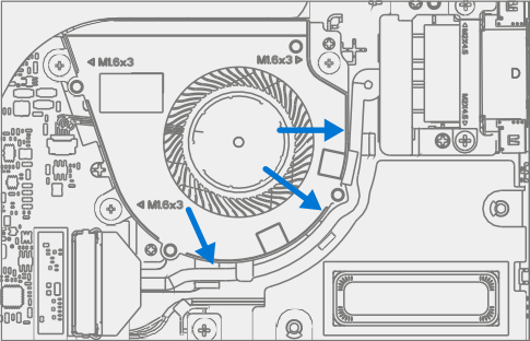
Remove Thermal Module (Heatsink) – Use a PH00 screwdriver to remove the four screws securing the thermal module and remove it from the PCBA.

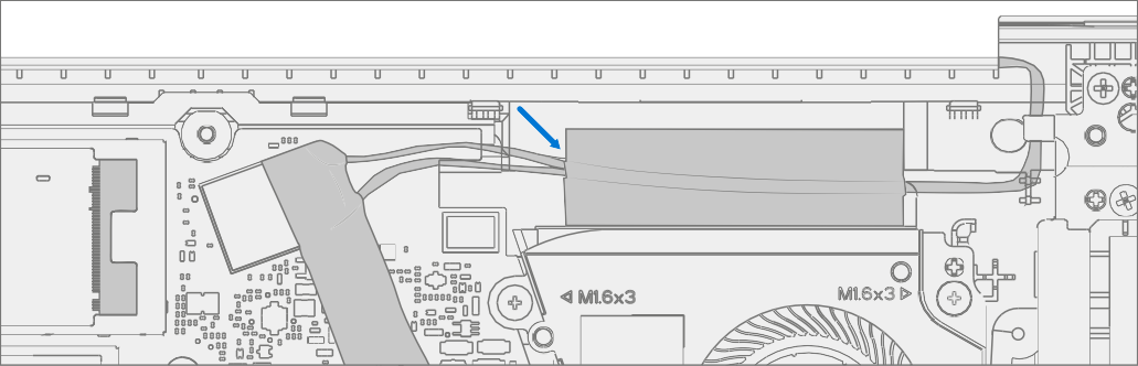
Disconnect Antenna cable – Using plastic tweezers remove the clear Mylar shield covering the antenna connectors. Disconnect the two Antenna cables located on Mainboard. Remove the black tape securing the antenna cables to the D-Bucket.


Disconnect Display connector – Lift up on the metal buckle. Then slide out the Display connector from the Mainboard connector.


Remove Two Inner Hinge Screws – Use a PH0 screwdriver to remove the two inner screws on the left and right hinges.
Set AB-Cover Display Angle to 90 deg for Safe Removal – Place the display module at an angle of about 90 degrees. Use a PH0 screwdriver to remove the two outer screws at the left and right hinges while holding the display with your free hand.

Remove AB-Cover from Device – Lift the display module straight up vertically until detached from the D-Bucket.
Procedure - Installation (AB-Cover Display Assembly)
Install AB-Cover – Set the new AB-Cover in place in the device chassis hinge wells and hold in place. Use a PH0 screwdriver to install 2 new MS20055I430 outer screws on each hinge. Screws should be installed until snug and seated, and then turned another 90 degrees (1/4 turn).


Install Two Inner Hinge Screws – Using a PH0 screwdriver, install 2 new inner MM20048I000 screws on the left and right hinges. Screws should be installed until snug and seated, and then turned another 90 degrees (1/4 turn).


Install LCD cable – Slide LCD cable into the Mainboard connector. Secure the cable with the metal buckle. Ensure the cable is routed below the metal tab near the hinge.

Connect Antenna cable – Carefully install two antenna connectors on the mainboard. Install a new clear Mylar shield over the antenna connectors. Secure the antenna cables to the D-Bucket with the supplied black tape.


Caution
Ensure the antenna with the shrink wrap ring is connected to the top interface.

Caution
Ensure the antenna cables are routed under the tab on the bracket near the hinge.

Install Thermal Module (Heatsink) – Gently clean off the residual thermal grease from the two IC chips with a lint free cloth. Make sure there are no contaminants or residual grease. Check that the thermal grease on the underside of the new thermal module is intact and not smeared. Place the thermal module over the two IC chips. Using a PH00 screwdriver Install 4 new MM16030I130 screws until snug and seated, and then turn another 45 degrees (1/8 turn).


Install C-Cover – Follow steps for Procedure – Installation (C-Cover Keyboard).
Important
Only snap the C-Cover in place. Don't secure C-Cover with screws.
Power On Device – Carefully place device top side up. Connect device to power supply, open display, and power on.
New AB-Cover TDM Calibration – On installation of a new AB-Cover TDM device final calibration relies on the successful completion of the TDM Replacement Mode. TDM calibration isn't required when installing the originally removed AB-Cover.
- Connect software tools USB drive with SDT to USB connector on device under repair.
- Run software tool – At the device OS, use Windows Explorer, navigate to USB drive, and run: SDT – Select Repair setup and validation. Run the Touch Display Calibration. Accept the restart prompt at the end of the tool process.
Important
This step must be carried out on the device successfully with installation of a new AB-Cover.
Install C-Cover Screws – Power off device. Close the AB-Cover and turn the unit over. Use a PH0 screwdriver to install seven new screws to secure the C-Cover as detailed on Procedure – Installation (C-Cover Keyboard).
Caution
Ensure the longer MS20055I430 screws are installed in the two corner locations under the rear foot pad as detailed in the Installation (C-Cover Keyboard).
Install Feet – Follow steps for Procedure – Installation (Non-Skid Feet).
Surflink Replacement Process
Preliminary Requirements
Important
Be sure to follow all special (bolded) notes of caution within each process section.
Required Tools and Components
- Tools:
- USB Thumb drive with SDT
- Plastic tweezers
- Spudger
- Plastic Opening Picks iFixit Opening Picks
- Plastic Opening tool iFixit Plastic Opening Tool
- Isopropyl Alcohol Dispenser (use only 70% IPA)
- PH0 Screwdriver
- PH00 Screwdriver
- Anti-static wrist strap (1M Ohm resistance)
- ESD-safe Surface Battery Cover (M1214771-001)
- Components:
- Surflink (Refer to Illustrated Service Parts List)
- MM20048I000 M2x4.8 Screws qty=6 (Supplied with Surflink)
- MS20055I430 M2x5.5 Screws qty=3 (Supplied with Surflink)
- MM20045I080 M2x4.5 Screws qty=2 (Supplied with Surflink)
- MM16030I130 M1.6x3 Screws qty=1 (Supplied with Surflink)
- Foil tape (Supplied with Surflink)
- Feet (Refer to Illustrated Service Parts List)
Prerequisite Steps:
- Power off device – Ensure device is powered off and disconnected from a power supply.
- General Safety – Check to make sure that general guidelines and ESD compliance steps are followed prior to opening device.
- Remove feet – Follow steps for Procedure – Removal (Non-Skid Feet).
- Remove C-Cover – Follow steps for Procedure – Removal (C-Cover Keyboard).
Procedure – Removal (Surflink)
Remove Right AB-Cover hinge Screws – Use a PH0 screwdriver to remove two screws securing the right AB-Cover hinge. Move the hinge up to make space for removal of the right bracket.


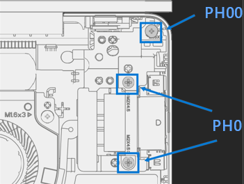
Remove Bracket – Use a PH0 screwdriver to remove two screws and a PH00 screwdriver to remove a third screw securing the right bracket. Remove the bracket from the D-Bucket.
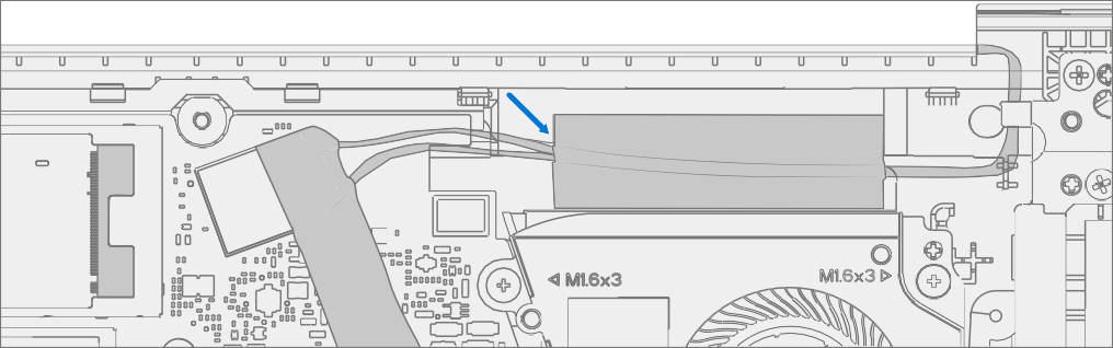
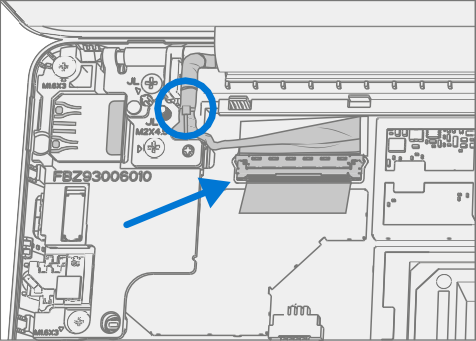
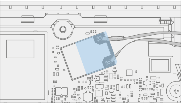
Remove Surflink – Remove foil tape. Use a spudger to unlock the Surflink cable connector and remove it from the mainboard. Remove the Surflink cable from the cooling fan shroud and then the Surflink assembly from the D-Bucket.


Procedure – Installation (Surflink)
Important
The AB-Cover hinge screws are of two lengths. Ensure the correct length screw is installed.
Refer to the hinge screw installation step for further details.
Install Surflink – Place the Surflink into the D-Bucket. Route the Surflink cable around the cooling fan shroud. Slide Surflink connector into the mainboard and press down on the locking tab.

Apply new foil tape as pictured below.

Install Bracket – Place right bracket in the D-Bucket over the Surflink. Use a PH0 screwdriver to install 2 new MM20045I080 screws and a PH00 screwdriver to a new MM16030I130 screw into the right bracket. Screws should be installed until snug and seated, and then turned another 45 degrees (1/8 turn).
Caution
Ensure the antenna cables are routed under the tab on the bracket.

Install Right AB-Cover hinge Screws – Tilt the hinge down over the right bracket. Use a PH0 screwdriver to install one MS20055I430 screw, and one MM20048I000 screw into the AB-Cover hinge. Screws should be installed until snug and seated, and then turned another 45 degrees (1/8 turn).

Install C-Cover – Follow steps for Procedure – Installation (C-Cover Keyboard).
Note
Only snap the C-Cover in place.
Power On Device – Carefully place device top side up. Connect device to power supply, open display, and power on.
Run SDT – Run SDT to ensure all device features and functions operate as expected. Refer to Surface Diagnostic Toolkit - User Guide for details on SDT. If SDT tests pass and no further repairs are to be performed on the device continue with the final assembly steps.
Install C-Cover Screws – Power off device. Close the AB-Cover and turn the unit over. Use a PH0 screwdriver to install seven new screws to secure the C-Cover as detailed on Procedure – Installation (C-Cover Keyboard).
Caution
Ensure the longer MS20055I430 screws are installed in the two corner locations under the rear foot pad as detailed in the Installation (C-Cover Keyboard).
Install Feet – Follow steps for Procedure – Installation (Non-Skid Feet).
Battery Replacement Process
Preliminary Requirements
Important
Be sure to follow all special (bolded) notes of caution within each process section.
Required Tools and Components
- Tools:
- USB Thumb drive with SDT
- Plastic tweezers
- Plastic Opening Picks
- Plastic Opening tool
- Isopropyl Alcohol Dispenser (use only 70% IPA)
- PH0 Screwdriver
- PH00 Screwdriver
- Anti-static wrist strap (1 MOhm resistance)
- Components:
- Battery (Refer to Illustrated Service Parts List)
- MM16035I040 M1.6x3.5 Screws qty=4 (Supplied with Battery) MS20055I430
- M2x5.5 Screws qty=2 (Supplied with Battery) MM20048I000
- M2x4.8 Screws qty=5 (Supplied with Battery)
- Feet (Refer to Illustrated Service Parts List)
Prerequisite Step
- Battery Status Check – Connect power supply, boot device, connect the
USB Thumb drive with SDT, and run SDT Battery tests. It's recommended
batteries showing any of the following should be replaced:
- PF Status of Non-Functional
- Wear value of 70% or less
- Cycle Count equal to or greater than a 1000
- Delta Voltage at or above 100 mV with state of charge 50% or greater
- Power off device – Ensure device is powered off and disconnected from a power supply.
- General Safety – Check to make sure that general guidelines and ESD compliance steps are followed prior to opening device.
- Remove feet – Follow steps for Procedure – Removal (Non-Skid Feet)
- Remove C-Cover – Follow steps for Procedure Removal C-Cover Keyboard.
Procedure – Removal (Battery)
Remove Battery Screws – Use a PH00 screwdriver to remove the four screws securing the battery.

Remove Battery – Carefully lift battery up and out of the D-Bucket.

Procedure – Installation (New Battery)
Warning
Only handle new battery using the finger loops.

Pre-Installation Device Inspection – Check D-bucket on both sides and device enclosure for any loose articles for foreign debris that may be present. Verify all removed screws are accounted for and haven't been misplaced in the device.
Insert New Battery – Using the finger loops carefully place the new battery into the D-Bucket. Ensure the tabs along the front edge are fully seated into the D-Bucket.


Install New Battery Screws – Using a PH00 screwdriver install 4 new MM16035I040 screws. Screws should be installed until snug and seated, and then turned another 45 degrees (1/8 turn). Carefully remove the liner.

Install C-Cover – Follow steps for Procedure – Installation (C-Cover Keyboard).
Note
Only snap the C-Cover in place.
New Battery Charging – New batteries are shipped and stored at low states of charge in compliance with shipping regulations. They should be charged to at least 50%. This step takes between 20 minutes and 1 hour and is needed to validate full functionality of the new battery. Carefully place device right-side up. Open device, connect the power supply, and power it on.
New Battery Authentication – New batteries require authentication. After charging the new battery to at least 50%. Connect the SDT USB drive. Run the SDT battery repair validation to ensure all features and functions operate as expected. Power off at completion of tests. Remove SDT USB drive and power supply. If no further repairs are required proceed to final steps.
Install New C-Cover Screws – Power off device. Close the AB-Cover and turn the unit over. Use a PH0 screwdriver to install seven new screws to secure the C-Cover as detailed on Procedure – Installation (C-Cover Keyboard).
Caution
Ensure the longer MS20055I430 screws are installed in the two corner locations under the rear foot pad as detailed in the Installation (C-Cover Keyboard).
Install Feet – Follow steps for Procedure – Installation (Non-Skid Feet) on Procedure – Installation (Non-Skid Feet).