Note
Access to this page requires authorization. You can try signing in or changing directories.
Access to this page requires authorization. You can try changing directories.
Warning
Review the General Safety Precautions and Battery Safety guidelines in their entirety before proceeding with any repair steps.
Important
Read this Guide in its entirety before starting any repairs. If at any point you're unsure or uncomfortable about performing the repairs, as detailed in this Guide, DO NOT proceed. Contact Microsoft for additional support options.
Warning
Failure to follow the instructions in this Guide, use of non-Microsoft (non-genuine), incompatible, or modified replacement parts, and/or failure to use proper tools could result in serious injury, death, and/or damage to the product or other property.
Prerequisite Steps
Steps outlined in this section should be conducted prior to starting any repair on a Surface device.
Power off device – Ensure the device is powered off completely and the battery has been fully discharged. Refer to the Repair-specific precautions and warnings section for guidelines. Once discharged, the device should be disconnected from all power sources.
ESD Prevention – Ensure ESD prevention steps and general guidelines are followed prior to opening the device. Refer to the ESD Prevention section for guidelines.
Position Device – To prevent damage to the device, ensure the device is placed on a clean surface free of debris.
Battery Warning
Warning
Please note that the battery bears the following warning label. Please heed the information provided on the label. This component cannot be easily replaced by user
Risk of fire or burning – contact Microsoft for assistance
Do not separate, detach, or remove the battery from its frame
Do not modify battery, its wiring, or connectors
Do not replace, short circuit, bend, crush, or puncture battery
Do not dispose of battery in fire or expose to high temperatures (+140°F/60°C)
For more information: aka.ms/surface-safety Rechargeable Lithium-Ion Polymer Battery Model name: 916QA145H 35Wh 7.6V ⎓ 4613mAh(NOM), 4473mAh(Rated) SMP, Made in China (Cell origin CosMX China)

Non-Skid Feet Replacement Process
Preliminary Requirements
Important
Be sure to follow all special (bolded) notes of caution within each process section.
Required Tools and Components
Tools:
- Plastic tool / spudger
- Isopropyl Alcohol Dispenser Bottle (use only 70% IPA)
- Cleaning swabs
Components:
- Feet FRU
Prerequisite Steps:
Power off device – Ensure device is powered off and disconnected from a power supply.
General Safety– Check to make sure that general guidelines and ESD compliance steps are followed prior to opening the device. Refer to Safety Guidelines section for details.
Position device – To prevent scratches, flip device over onto a clean surface free of debris with the device bottom facing up for access to the feet for removal.
Procedure - Removal (Non-Skid Feet)
Feet removal – Use plastic tool / spudger to lift one edge of each foot. Ensure all adhesive tape remnants and glue residue are removed. Clean the D-Bucket foot recesses with 70% Isopropyl Alcohol.

Procedure - Installation (Non-Skid Feet)
Prepare new foot and press into place – To install each foot, remove protective sheet to expose adhesive on foot. Press foot into D-Bucket recess. Repeat for each foot. Note the back feet are larger.

Inspect for anomalies – Inspect each foot to ensure no cosmetic damage or gaps between the foot and the D-bucket foot recesses exist.
C-Cover Keyboard Assembly Replacement Processes
Preliminary Requirements
Important
Be sure to follow all special (bolded) notes of caution within each process section.
Required Tools and Components
Tools:
- USB Thumb drive with Surface Diagnostic Toolkit Configuration Files
- Plastic Opening tool / Spudger
- Torx T6 driver
- Anti-static wrist strap (1M Ohm resistance)
Components:
- C-Cover Keyboard Assembly, Refer to Illustrated Service Parts List)
- C-Cover Screws (MM20065I030) Qty. 7
Prerequisite Steps:
Power off device – Ensure device is powered off and disconnected from a power supply.
General Safety– Check to make sure that general guidelines and ESD compliance steps are followed prior to opening device. Refer to Safety Guidelines for details.
Position device – Place device onto a clean surface free of debris with the bottom facing up.
Procedure - Removal (C-Cover)
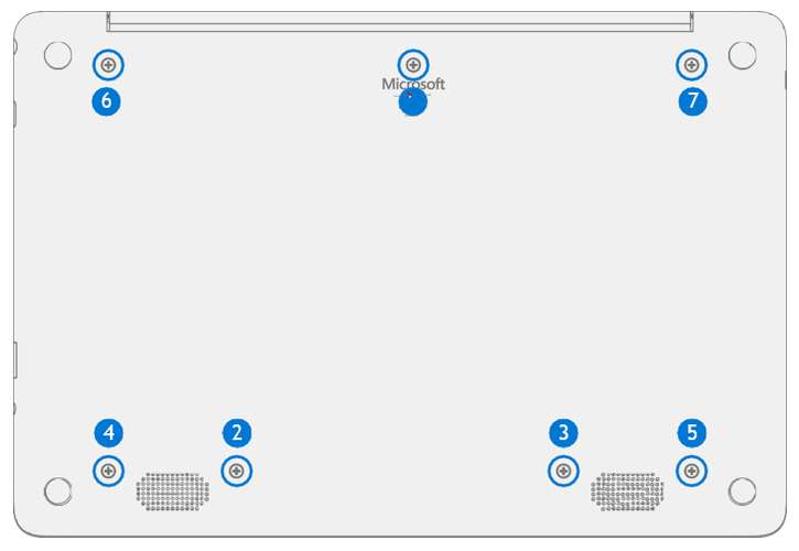
Remove C-Cover screws – Using a Torx T6 driver remove the 7 screws from the D-Bucket.

Caution
All 7 screws must be removed before starting C-Cover removal.
Separate C-Cover from device – Separation is a multistep process.
Using your fingers or a plastic tool / spudger release the D-Bucket snaps along the back edge between the display hinges.

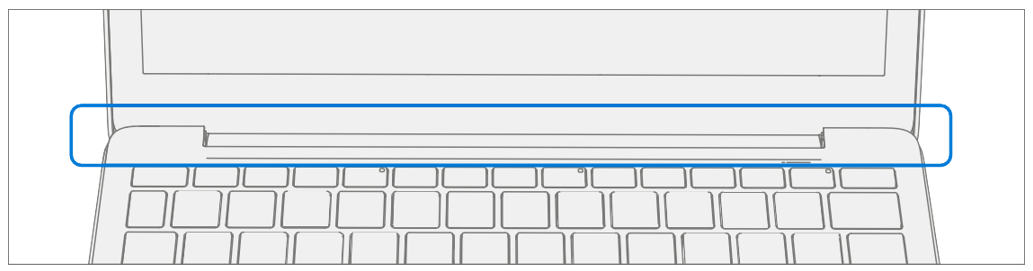
Place the device topside up and open the display. Using your fingers or a plastic tool / spudger release the C-Cover snaps along the edge below the display.
Using your fingers or a plastic tool / spudger release the C-Cover snaps along the left and right sides.

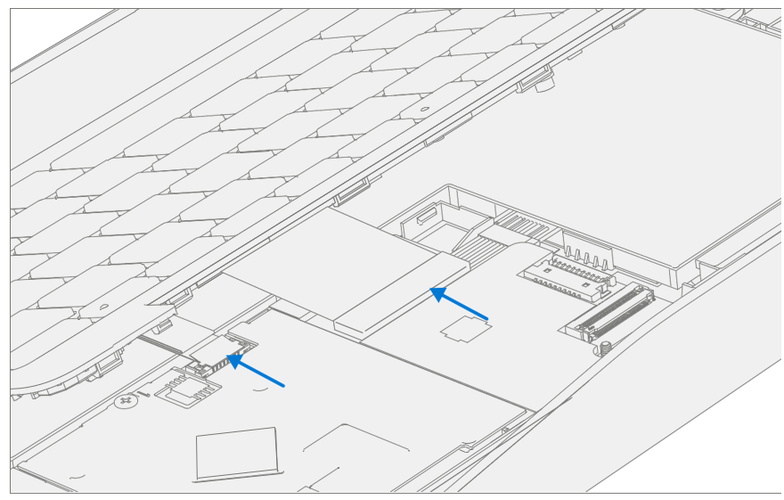
Disconnect Battery Cable – Holding the C-Cover at an angle use a plastic tool / spudger to disconnect the battery cable from the PCBA.
Caution
Do not pull the C-cover apart beyond 45-degrees otherwise damage to C-cover FPC could occur.

Disconnect C-Cover FPCs – Holding the C-Cover at an angle use a plastic tool / spudger to disconnect the FPCs from the PCBA.
Procedure - Installation (C-Cover)
Pre-installation Device Inspection
Warning
Verify the battery’s condition, refer to the M1153910 in Device Battery Inspection process for details. Devices exhibiting battery issues as outlined in the Battery Inspection Process require battery replacement.
Warning
Verify the condition of LDI (Liquid Damage Indicators) on the Audio Jack and PCBA. Any color other than white indicates liquids have entered the device. The LDI on the Audio Jack is viewable from the outside of the device. The LDI on the PCBA is along the top edge of the heatsink. Devices exhibiting LDI require whole unit replacement.
Check for unexpected items within device – Check C-Cover (both sides) and device enclosure for any loose articles that may be present inadvertently on the C-Cover or within the device enclosure areas.
- Carefully inspect the area around battery specifically for any foreign objects.
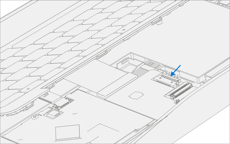
Connect C-Cover FPCs – Hover the C-Cover over the device while assembling the C-Cover FPCs to the PCBA.
Caution
Be sure that FPC bends fall in place properly as pre-bent and no folds or creases are created during re-assembly of C-Cover.

Connect Battery Cable – Holding the C-Cover at an angle connect the battery cable to the PCBA.
Align the C-Cover – Properly align the C-Cover to the device using the front edge. Place the C-cover back onto the device. Press down along the outside edges to engage snaps. Press down on the center of the keyboard to engage the keyboard hook.

Run SDT – Power on device and connect USB drive with SDT Configuration Files. Run SDT to ensure all device features and functions operate as expected. If no further repairs are required proceed to final steps.
Install new C-Cover screws – Power off device, close display, and place it upside down. Using a Torx T6 driver install 7 new MM20065I030 screws into the D-Bucket. Follow the installation order pictured below. Turn all screws until just snug and seated, and then turn another 45-degrees (1/8 turn) or until fully fastened.
Power Port Replacement Processes
Preliminary Requirements
Important
Be sure to follow all special (bolded) notes of caution within each process section.
Required Tools and Components
Tools:
- USB Thumb drive with Surface Diagnostic Toolkit Configuration Files
- Plastic Opening tool / Spudger
- PH0 driver
- Torx T6 driver
- Small suction cups
- Anti-static wrist strap (1M Ohm resistance)
Components:
- Battery (Illustrated Service Parts List)
- C-Cover Screws (MM20065I030) Qty. 7
- Power Port Screws (MS20025I070) Qty. 3
Prerequisite Steps:
- Power off device – Ensure device is powered off and disconnected from a power supply.
- General Safety– Check to make sure that general guidelines and ESD compliance steps are followed prior to opening device. Refer to Safety Guidelines for details.
- Position device – Place device onto a clean surface free of debris with the bottom facing up.
- Remove C-cover – Follow steps for Procedure - Removal (C-cover Keyboard) on Procedure - Removal (C-cover)
Procedure - Removal (Power Port)
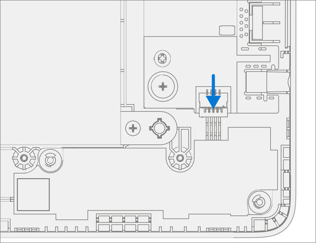
Disconnect DC Power Cable – Using a plastic tool / spudger to disconnect the DC power cable from the PCBA.

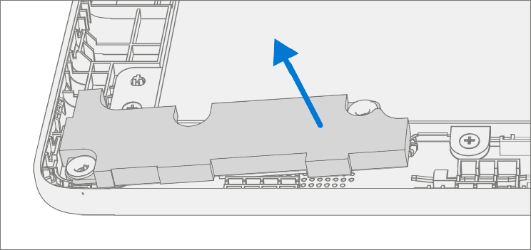
Remove USB Bracket – Using a PH0 driver remove the two screws from the USB bracket. Remove the bracket from the D-Bucket.

Remove DC Power Port – Using a PH0 driver remove the screw from the DC power port. Remove the DC power port from the D-Bucket.

Procedure - Installation (Power Port)
Install DC Power Port – Place the new DC power port into the D-Bucket. Ensure the port is aligned with the hole in the D-Bucket. Using a PH0 driver install a new MS20025I070 screw into the DC power port. Turn the screw until just snug and seated, and then turn another 45-degrees (1/8 turn) or until fully fastened.

Install USB Bracket – Place the USB bracket into the D-Bucket. Using a PH0 driver install two new MS20025I070 screws into the USB bracket. Turn all the screws until just snug and seated, and then turn another 45-degrees (1/8 turn) or until fully fastened.

Connect DC Power Cable – Connect the DC power cable to the PCBA
Install C-cover – Follow steps for Procedure – Installation (C-Cover Keyboard) on Procedure – Installation (C-Cover Keyboard). Leaving C-Cover screws uninstalled.
Run SDT – Power on device and connect USB drive with SDT Configuration Files. Run SDT to ensure all device features and functions operate as expected. If no further repairs are required, proceed to final steps.
Install new C-Cover screws – Install new MM20065I030 Screws as detailed on Procedure – Installation (C-Cover).
Battery Replacement Processes
Preliminary Requirements
Important
Be sure to follow all special (bolded) notes of caution within each process section.
Required Tools and Components
Tools:
- USB Thumb drive with Surface Diagnostic Toolkit Configuration Files
- Plastic Opening tool / Spudger
- PH0 driver
- Torx T6 driver
- Small suction cups
- Anti-static wrist strap (1M Ohm resistance)
Components:
- Battery (Refer to Illustrated Service Parts List)
- C-Cover Screws (MM20065I030) Qty. 7
- Battery Screws (MS20025I070) Qty. 8
Prerequisite Steps:
Battery Status Check – Connect power supply, boot device, connect the USB Thumb drive with SDT, and run SDT Battery tests. It is recommended batteries showing any of the following should be replaced:
- PF Status of Non Functional
- Wear value of 70% or less
- Cycle Count equal to or greater than a 1000
- Delta Voltage at or above 100 mV with state of charge 50% or greater
Power off device – Ensure device is powered off and disconnected from a power supply.
General Safety– Check to make sure that general guidelines and ESD compliance steps are followed prior to opening device. Refer to Safety Guidelines for details.
Position device – Place device onto a clean surface free of debris with the bottom facing up.
Remove C-cover – Follow steps for Procedure - Removal (C-cover Keyboard) on Procedure - Removal (C-cover).
Procedure - Removal (Battery)
Remove Battery screws – Using a PH0 driver remove the 8 screws from the Battery frame.

Remove Battery from device – Carefully remove the battery from the device using two small suction cups.
Procedure - Installation (Battery)
Pre-installation Device Inspection – Check D-bucket (both sides) and device enclosure for any loose articles that may be present.
- Check for and remove any foreign objects that the magnets may have attracted.
- Verify all removed screws are accounted for and have not been misplaced in the device.
- Loose screws should never be stored on the C-Cover or in the D-Bucket.
Install New Battery into device – Using the loops carefully install the new battery into the device.

Install New Battery Screws – Using a PH0 driver install 8 new MS20025I070 screws into the battery frame. Follow the installation order pictured below. Turn all screws until just snug and seated, and then turn another 45-degrees (1/8 turn) or until fully fastened. Carefully remove the liner with handling loops.

Install C-cover – Follow steps for Procedure – Installation (C-Cover Keyboard) on Procedure - Installation (C-Cover Keyboard). Leaving C-Cover screws uninstalled.
New Battery Charging – New batteries are shipped and stored at low states of charge in compliance with shipping regulations. They should be charged to at least 50%. This step will take between 20 minutes and 1 hour and is needed to validate full functionality of the new battery. Carefully place device right-side up. Open device, connect the power supply, and power it on.
New Battery Authentication – New batteries require authentication. After charging the new battery to at least 50%, connect the SDT Configuration Files USB drive. Run the SDT battery repair validation to ensure all features and functions operate as expected. Power off at completion of tests. Remove SDT Configuration Files USB drive and power supply. If no further repairs are required, proceed to final steps.
Install new C-Cover screws – Install new MM20065I030 Screws as detailed on Procedure – Installation (C-Cover).
WiFi Module Replacement Processes
Preliminary Requirements
Important
Be sure to follow all special (bolded) notes of caution within each process section.
Required Tools and Components
Tools:
- USB Thumb drive with Surface Diagnostic Toolkit Configuration Files
- Plastic Opening tool / Spudger
- PH0 driver
- Torx T6 driver
- Anti-static wrist strap (1M Ohm resistance)
Components:
- WiFi Module (Refer to Illustrated Service Parts List)
- C-Cover Screws (MM20065I030) Qty. 7
- WiFi Module Screw (MS20025I070) Qty. 1
Prerequisite Steps:
Power off device – Ensure device is powered off and disconnected from a power supply.
General Safety– Check to make sure that general guidelines and ESD compliance steps are followed prior to opening device. Refer to Safety Guidelines for details.
Position device – Place device onto a clean surface free of debris with the bottom facing up.
Remove C-cover – Follow steps on Procedure - Removal (C-cover)
Procedure - Removal (WiFi Module)
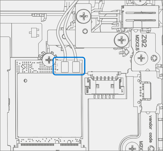
Disconnect Antenna Cables – Using a plastic tool / spudger remove the mylar cover from the WiFi Module. Disconnect the two antenna cables from the WiFi Module.

Remove WiFi Module screw – Using a PH0 driver remove the screw from the WiFi Module.

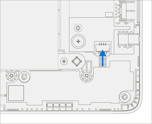
Remove WiFi Module – Pull the WiFi Module out of the PCBA connector.

Procedure - Installation (WiFi Module)
Install New WiFi Module– Install the WiFi Module into the PCBA connector.

Install New WiFi Module screw – Using a PH0 driver install a new MS20025I070 screw onto the WiFi Module. Turn the screw until just snug and seated, and then turn another 45-degrees (1/8 turn) or until fully fastened.

Connect Antenna Cables – Connect the antenna cables onto the WiFi Module as pictured below. Ensure the white cable is installed on the right side connector and the black cable is installed on the left side connector.

Install Antenna Cable Mylar – Install a new mylar cover onto the WiFi Module as pictured below.

Install C-cover – Follow steps for Procedure – Installation (C-Cover Keyboard) on Procedure - Installation (C-Cover Keyboard). Leaving C-Cover screws uninstalled.
Run SDT – Power on device and connect USB drive with SDT Configuration Files. Run SDT to ensure all device features and functions operate as expected. If no further repairs are required, proceed to final steps.
Install new C-Cover screws – Install new MM20065I030 Screws as detailed on Procedure – Installation (C-Cover). .
Motherboard (PCBA) Replacement Process
Preliminary Requirements
Important
Be sure to follow all special (bolded) notes, cautions, and warnings in each process section.
Required Tools and Components
Tools:
- USB Thumb drive with Surface Diagnostic Toolkit Configuration Files
- Plastic Opening tool / Spudger
- PH0 driver
- Torx T6 driver
- Anti-static wrist strap (1M Ohm resistance)
Components:
- Motherboard (PCBA), Refer to Illustrated Service Parts List
- C-Cover Screws (MM20065I030) Qty. 7
- USB Bracket / WiFi Module Screws (MS20025I070) Qty. 3
- PCBA Screws (MS20015I220) Qty. 2
Prerequisite Steps:
Power off device – Ensure device is powered off and disconnected from a power supply.
General Safety– Check to make sure that general guidelines and ESD compliance steps are followed prior to opening device. Refer to Safety Guidelines for details.
Position device – Place device onto a clean surface free of debris with the bottom facing up.
Remove C-cover – Follow steps for Procedure - Removal (C-cover Keyboard) on Procedure - Removal (C-cover)
Remove WiFi Module – Follow steps on Procedure - Removal (WiFi Module)
Procedure - Removal (Motherboard PCBA)
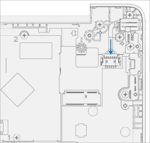
Disconnect DC Power Cable – Using a plastic tool / spudger to disconnect the DC power cable from the PCBA.
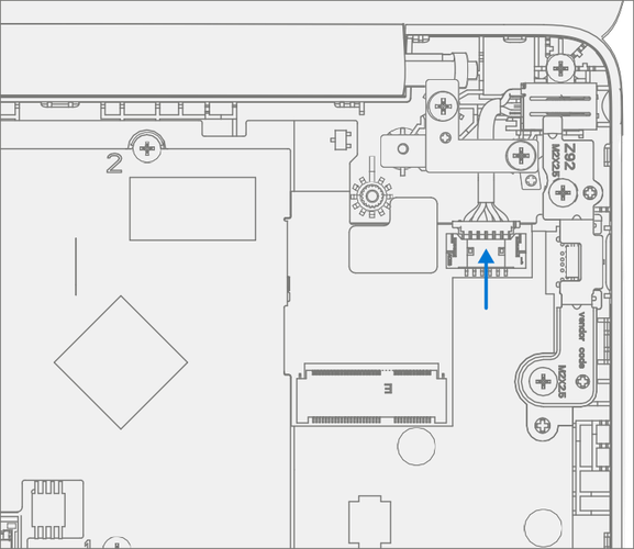
Disconnect Speaker Cable – Using a plastic tool / spudger disconnect the speaker cable from the PCBA.

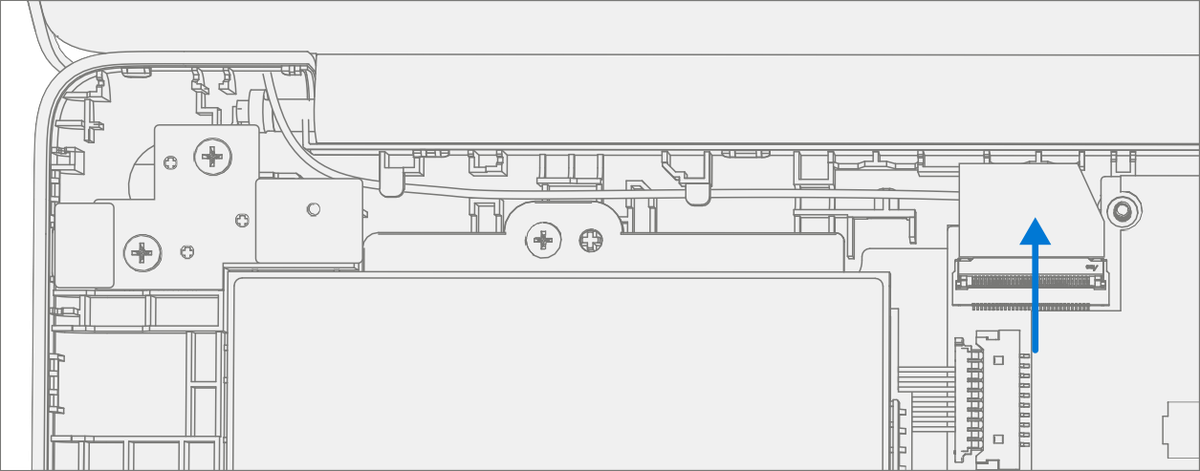
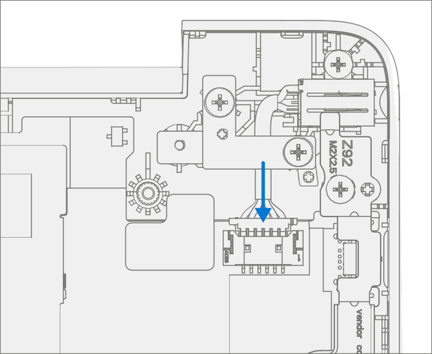
Disconnect AB-Cover Cable – Using a plastic tool / spudger unlock the AB-Cover cable connector. Remove AB-Cover cable from the PCBA.
Remove USB Bracket – Using a PH0 driver, remove the two screws from the USB bracket. Remove the bracket from the D-Bucket.

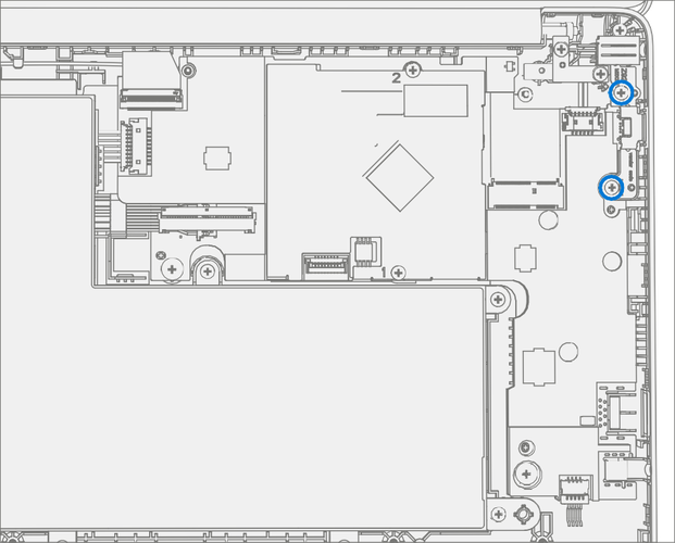
Remove PCBA screws – Using a PH0 driver remove the two screws from the PCBA.

Remove PCBA – Remove PCBA from the D-Bucket.

Procedure - Installation (Motherboard PCBA)
Important
Only a Microsoft PCBA of like configuration should be replaced in the device.
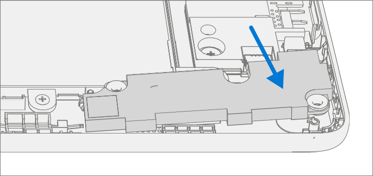
Install PCBA – Align PCBA into the D-Bucket. Ensure USB and audio ports are aligned to the holes in the D-Bucket. The PCBA should be centered on the locating posts as pictured below.

Install New PCBA screws – Verify the battery, display, antenna, power, and speaker cables are not captured under the PCBA. Using a PH0 driver install two new MS20015I220 screws into the PCBA. Turn all the screws until just snug and seated, and then turn another 45-degrees (1/8 turn) or until fully fastened.

Install USB Bracket – Place the previously removed USB bracket into D-Bucket. Using a PH0 driver install two new MS20025I070 screws into the USB bracket. Turn all the screws until just snug and seated, and then turn another 45-degrees (1/8 turn) or until fully fastened.
Connect AB-Cover Cable – Connect the AB-Cover cable into the PCBA. Ensure the cable is fully seated and locked in the connector.

Connect Speaker Cable – Connect the speaker cable onto the PCBA.
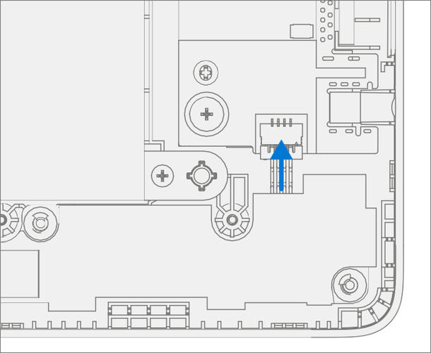
Connect DC Power Cable – Connect the DC power cable into the PCBA.
Install WiFi Module – Install WiFi Module as detailed Procedure – Installation (WiFi Module) on Procedure - Installation (WiFi Module).
Install C-cover – Install C-Cover as detailed on Procedure - Installation (C-Cover Keyboard). Leave C-Cover screws uninstalled.
Run SDT – Power on device and connect USB drive with SDT Configuration Files. Run SDT to ensure all device features and functions operate as expected. If no further repairs are required, proceed to final steps.
Battery Authentication – Authenticate new battery as detailed in Procedure – Installation (Battery), step 6 on Procedure – Installation (Battery).
Install new C-Cover screws – Install new MM20065I030 Screws as detailed, step 7 on Procedure – Installation (C-Cover).
Important
To get hardware hash for enrollment into Intune follow instructions outlined here.
Speaker Replacement Processes
Preliminary Requirements
Important
Be sure to follow all special (bolded) notes of caution within each process section.
Required Tools and Components
Tools:
- USB Thumb drive with Surface Diagnostic Toolkit Configuration Files
- Plastic Opening tool / Spudger
- PH0 driver
- Torx T6 driver
- Anti-static wrist strap (1M Ohm resistance)
Components:
- Speaker Assembly (Refer to Illustrated Service Parts List)
- C-Cover Screws (MM20065I030) Qty. 7
Prerequisite Steps:
Power off device – Ensure device is powered off and disconnected from a power supply.
General Safety– Check to make sure that general guidelines and ESD compliance steps are followed prior to opening device. Refer to Safety Guidelines for details.
Position device – Place device onto a clean surface free of debris with the bottom facing up.
Remove C-cover – Follow steps for Procedure - Removal (C-cover Keyboard) on Procedure - Removal (C-cover).
Procedure - Removal (Speakers)
Disconnect Speaker Cable – Using a plastic tool / spudger disconnect the speaker cable from the PCBA.
Remove Speakers from device – Separation is a multistep process.
Lift the right speaker form the two D-Bucket posts.

Unhook and release speaker cable from the D-Bucket.

Lift the left speaker from the two D-Bucket posts.
Procedure - Installation (Speakers)
Install Speakers into device – Installation is a multistep process.
Install the left speaker onto the two D-Bucket posts.

Route and hook the speaker cable onto the D-Bucket.

Install the right speaker onto the two D-Bucket posts.
Connect Speaker Cable – Connect the speaker cable onto the PCBA.
Install C-cover – Follow steps for Procedure – Installation (C-Cover Keyboard) on Procedure - Installation (C-Cover Keyboard). Leaving C-Cover screws uninstalled.
Run SDT – Power on device and connect USB drive with SDT Configuration Files. Run SDT to ensure all device features and functions operate as expected. If no further repairs are required, proceed to final steps.
Install new C-Cover screws – Install new MM20065I030 Screws as detailed on Procedure – Installation (C-Cover).
AB-Cover Display Assembly Replacement Processes
Preliminary Requirements
Important
Be sure to follow all special (bolded) notes of caution within each process section.
Required Tools and Components
Tools:
- USB Thumb drive with Surface Diagnostic Toolkit Configuration Files
- Plastic Opening tool / Spudger
- PH0 driver
- Torx T6 driver
- Anti-static wrist strap (1M Ohm resistance)
Components:
- AB-Cover Display Assembly (Refer to Illustrated Service Parts List)
- C-Cover Screws (MM20065I030) Qty. 7
- AB-Cover Hinges (MS25040I060) Qty. 4
Prerequisite Steps:
Power off device – Ensure device is powered off and disconnected from a power supply.
General Safety– Check to make sure that general guidelines and ESD compliance steps are followed prior to opening device. Refer to Safety Guidelines for details.
Position device – Place device onto a clean surface free of debris with the bottom facing up.
Remove C-cover – Follow steps on Procedure - Removal (C-cover).
Procedure - Removal (AB-Cover Display Assembly)
Position AB-Cover – Set AB-Cover to 90-degrees.

Disconnect Antenna Cables – Using a plastic tool / spudger remove the mylar cover from the WiFi Module. Disconnect the two antenna cables from the WiFi Module.

Disconnect AB-Cover Cable – Using a plastic tool / spudger unlock the AB-Cover cable connector. Remove AB-Cover cable from the PCBA. Carefully remove cable from the D-Bucket channels and hooks.

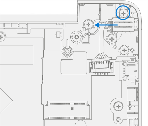
Remove AB-Cover hinge screws – Using a PH0 driver remove the two screws from the right AB-Cover hinge. While holding the AB-Cover with one hand remove the two screws from the left AB-Cover hinge. Remove the AB-Cover Display Assembly from the D-Bucket.

Procedure - Installation (AB-Cover Display Assembly)
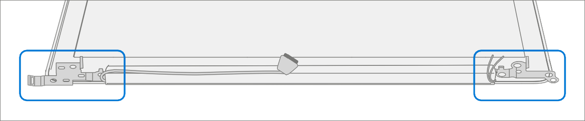
Position New AB-Cover hinges – Set AB-Cover hinges to 90-degrees.
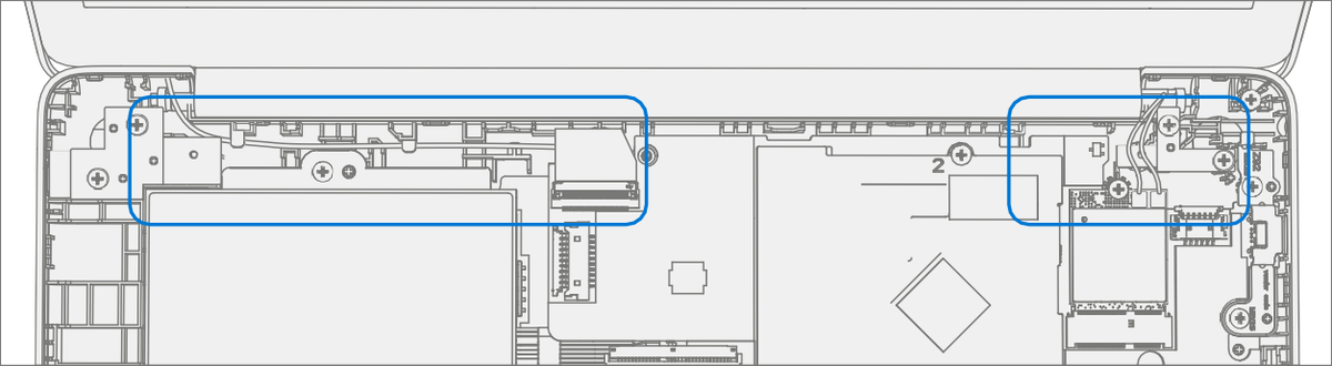
Install New AB-Cover Display Assembly – Align AB-Cover hinges into the D-Bucket. Ensure display and antenna cables are routed as pictured below.
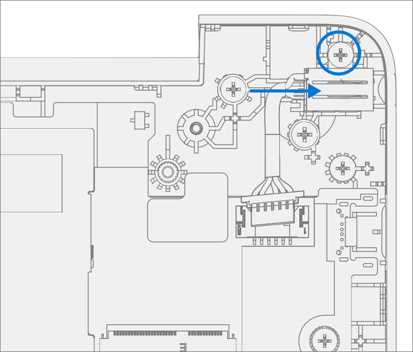
Install New AB-Cover hinge screws – Using a PH0 driver install two new MS25040I060 screws into the left hinge. Install two new MS25040I060 screws into the right hinge. Turn all the screws until just snug and seated, and then turn another 45-degrees (1/8 turn) or until fully fastened.

Connect AB-Cover Cable – Carefully route the cable into the D-Bucket channels and hooks. Connect the AB-Cover cable into the PCBA. Ensure the cable is fully seated and locked in the connector.

Connect Antenna Cables – Connect the antenna cables onto the WiFi Module as pictured below. Ensure the white cable is installed on the right side connector and the black cable is installed on the left side connector.
Install Antenna Cable Mylar – Install a new mylar cover onto the WiFi Module as pictured below.

Install C-cover – Follow steps on Procedure - Installation (C-Cover Keyboard). Leaving C-Cover screws uninstalled.
Run SDT – Power on device and connect USB drive with SDT Configuration Files. Run SDT to ensure all device features and functions operate as expected. If no further repairs are required proceed to final steps.
Install new C-Cover screws – Install new MM20065I030 Screws as detailed on Procedure – Installation (C-Cover).
D-Bucket Replacement Process
Preliminary Requirements
Important
Be sure to follow all special (bolded) notes of caution within each process section.
Required Tools and Components
Tools:
- USB Thumb drive with Surface Diagnostic Toolkit Configuration Files
- Plastic Opening tool / Spudger
- PH0 driver
- Torx T6 driver
- Anti-static wrist strap (1M Ohm resistance)
Components:
- D-Bucket (Refer to Illustrated Service Parts List)
- C-Cover Screws (MM20065I030) Qty. 7
- USB Bracket / WiFi Module / DC Power Port / Battery Screws (MS20025I070) Qty. 12
- PCBA Screws (MS20015I220) Qty. 2
- AB-Cover Hinges (MS25040I060) Qty. 4
Prerequisite Steps:
Important
The serial number for this device model is located on its original cover. To keep track of the device’s serial number, please record it using waterproof ink (Location Link) on a sticker or label and apply the sticker or label to an easily accessible area on the device exterior. The serial number cannot be added permanently to a replacement part. Microsoft may have provided a label for this use in the replacement part’s packaging.
Power off device – Ensure device is powered off and disconnected from a power supply.
General Safety– Check to make sure that general guidelines and ESD compliance steps are followed prior to opening device. Refer to Safety Guidelines for details.
Position device – Place device onto a clean surface free of debris with the bottom facing up.
Remove C-cover – Follow steps on Procedure - Removal (C-cover)
Remove Power Port – Follow steps on Procedure - Removal (Power Port).
Remove Battery – Follow steps for on Procedure - Removal (Battery)
Remove WiFi Module – Follow steps on Procedure - Removal (WiFi Module)
Remove Motherboard - Follow steps on Procedure - Removal (Motherboard PCBA)
Remove Speakers – Follow steps on Procedure - Removal (Speakers)
Remove AB-Cover - Follow steps on Procedure - Removal (AB-Cover Display Assembly)
Procedure - Removal (D-Bucket)
Disconnect DC Power Cable – Using a plastic tool / spudger to disconnect the DC power cable from the PCBA.
Remove USB Bracket – Using a PH0 driver, remove the two screws from the USB bracket. Remove the bracket form the D-Bucket.
Remove DC Power Port – Using a PH0 driver remove the screw from the DC power port. Remove the DC power port from the D-Bucket.
Remove PCBA screws – Using a PH0 driver remove the two screws from the PCBA.

Remove PCBA – Remove PCBA from the D-Bucket.

Procedure - Installation (New D-Bucket)
Install PCBA – Align PCBA into the D-Bucket. Ensure USB and audio ports are aligned to the holes in the D-Bucket. The PCBA should be centered on the locating posts as pictured below.

Install New PCBA screws – Using a PH0 driver install two new MS20015I220 screws into the PCBA. Turn all the screws until just snug and seated, and then turn another 45-degrees (1/8 turn) or until fully fastened.

Install DC Power Port – Place the DC power port removed from the old D-Bucket into the new D-Bucket. Ensure the port is aligned with the hole in the D-Bucket. Using a PH0 driver install a new MS20025I070 screw into the DC power port. Turn the screw until just snug and seated, and then turn another 45-degree (1/8 turn) or until fully fastened.
Install USB Bracket – Place the USB bracket removed from the old D-Bucket into the new D-Bucket. Using a PH0 driver install two new MS20025I070 screws into the USB bracket. Turn all the screws until just snug and seated, and then turn another 45-degrees (1/8 turn) or until fully fastened.

Connect DC Power Cable – Connect the DC power cable into the PCBA.

Install WiFi Module – Follow steps on Procedure – Installation (WFi Module)
Install Speakers – Follow steps on Procedure – Installation (Speakers)
Install Battery – Follow steps on Procedure – Installation (Battery).
Install AB-Cover – Follow steps on Procedure - Installation (AB-Cover Display Assembly).
Install C-cover – Follow steps for Procedure – Installation (C-Cover Keyboard) on Procedure – Installation (C-Cover Keyboard). Leaving C-Cover screws uninstalled.
Run SDT – Power on device and connect USB drive with SDT Configuration Files. Run SDT to ensure all device features and functions operate as expected. If no further repairs are required, proceed to final steps.
Install new C-Cover screws – Install new MM20065I030 Screws as detailed on Procedure – Installation (C-Cover).