Note
Access to this page requires authorization. You can try signing in or changing directories.
Access to this page requires authorization. You can try changing directories.
Warning
Review the General Safety Precautions and Battery Safety guidelines in their entirety before proceeding with any repair steps.
Important
Read this Guide in its entirety before starting any repairs. If at any point you're unsure or uncomfortable about performing the repairs, as detailed in this Guide, DO NOT proceed. Contact Microsoft for more support options.
Warning
Failure to follow the instructions in this Guide, use of non-Microsoft (nongenuine), incompatible, or modified replacement parts, and/or failure to use proper tools could result in serious injury, death, and/or damage to the product or other property.
Prerequisite Steps
Steps outlined in this section should be conducted before starting any repair on a Surface device.
Power off device – Ensure the device is powered off completely and the battery has been fully discharged. Refer to the Repair-specific precautions and warnings section for guidelines. Once discharged, the device should be disconnected from all power sources.
ESD Prevention – Ensure ESD prevention steps and general guidelines are followed before opening the device. Refer to the ESD Prevention section for guidelines.
Position Device – To prevent damage to the device, ensure the device is placed on a clean surface free of debris.
Non-Skid Feet Replacement Process
Preliminary Requirements
Important
Be sure to follow all special (bolded) notes of caution within each process section.
Required Tools and Components
- All tools required for repair are listed under Service Tools and Jigs.
- All parts required for this repair will be provided in the CRU kit being purchased. CRU kits are listed on the Illustrated Parts List.
Important
Feet replacements must be ordered for each repair.
Prerequisite Steps
- Power Off Device – Ensure device is powered off by fully discharging the battery. Refer to Repair-Specific Precautions and Warnings section for details. Ensure device is disconnected from a power supply and all cables and drives are removed.
- ESD Prevention – Check to make sure that general guidelines and ESD Prevention steps are followed before opening device. Refer to ESD Prevention section for details.
- Position device – Place device onto a clean surface free of debris with the bottom facing up.
Procedure - Removal (Feet)
Remove Feet – Use a plastic tool to pry up the foot from one end and then peel to remove. Repeat for the other foot.

Cleaning – Remove any adhesive tape remnants from the chassis and clean off any glue residue with 70% or greater Isopropyl Alcohol.
Procedure - Installation (Feet)
Important
Once removed, the feet must be replaced with new ones.
Device Orientation – Place device onto a clean surface that has been wiped down with an ESD Safe cleaner and is free of debris, with the bottom facing up.
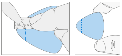
Apply New Feet – Remove the liners to the adhesive strip and place the right side of the foot into the groove ensuring that the alignment post fits into the chassis hole. Loosely place the rest of the foot down making sure that the left alignment post fits in the corresponding chassis hole. Repeat the same steps for the remaining foot.

Securing New Feet – Place a ruler over one of the feet. Press down on the ruler with several fingers spaced along the length of the ruler for about 30 seconds to secure the foot. Repeat the same steps for the remaining foot.

Chassis & Battery Replacement Process
Preliminary Requirements
Important
Be sure to follow all special (bolded) notes of caution within each process section.
Required Tools and Components
- All tools required for repair are listed under Service Tools and Jigs
- All parts required for this repair will be provided in the CRU kit being purchased. CRU kits are listed on the Illustrated Parts List.
Important
Feet replacements must be ordered for each repair.
Prerequisite Steps
- Power off device – Ensure device is powered off by fully discharging the battery. Refer to Repair-Specific Precautions and Warnings section for details. Ensure device is disconnected from a power supply and all cables and drives are removed.
- ESD Prevention – Check to make sure that general guidelines and ESD Prevention steps are followed before opening device. Refer to ESD Prevention section for details.
- Position device – Place device onto a clean surface free of debris with the bottom facing up.
- Remove Feet – Refer to Procedure – Removal (Feet).
- Note device serial number – The serial number for this device model is located on its original cover. Refer to Device Identity Information (page 6). To keep track of the device’s serial number, record it using waterproof ink on a sticker or label and apply the sticker or label to an easily accessible area on the device exterior. The serial number can't be added permanently to a replacement part. Microsoft might have provided a label for this use in the replacement part’s packaging.
Procedure - Removal (Chassis + Battery)
Remove Chassis screws – Using a 3IP (Torx-Plus) driver remove the 7 screws from the foot wells.

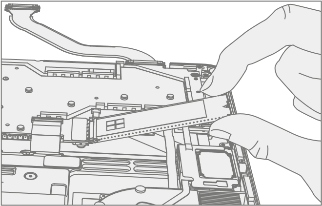
Mark Tool Pick Depth – To prevent damage to internal components use a metric ruler to draw a 13-mm mark on two plastic picks.
Warning
Don't insert picks beyond the 13-mm mark. Failure to do so can lead to picks contacting the battery and causing damage.
Separate Cosmetic Plate Sides – Lift corner of cosmetic plate with a pry tool, then insert a plastic opening pick and work around the outer edge of the chassis until you reach the front of the device. Leave left opening pick in place and repeat process on the right side of the cosmetic plate.
Important
If replacing the Chassis + Battery, the old cosmetic plate might not be reused. A new Cosmetic Plate must be used.

Separate Cosmetic Plate Front – Lift back of chassis slightly from the rest of the device. Work an opening pick along the front edge of the device to fully separate the chassis from the Keyboard Assembly.
Important
Make sure to keep the opening pick horizontal to the chassis. Failure to do so might damage the pen charger shim under the cosmetic plate. Damage to the shim requires its replacement.

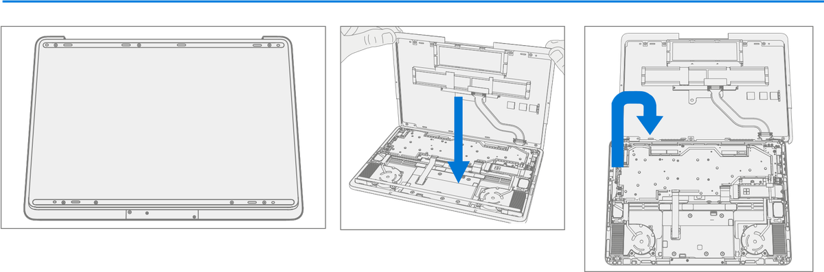
Separate Chassis from device – Lift the Chassis off and place it above the device, rotating about the hinge so the battery cable isn’t pulled tight. The battery is facing up.
Important
Don't attempt to open with sharp objects, this might result in severe personal injury or property damage.
Important
Only handle Chassis + Battery assembly by the metal of the chassis. Bending, twisting, or impacting battery might damage the battery, damage the device, and/or result in severe personal injury or property damage. Always use two hands when handling the Chassis + Battery assembly.
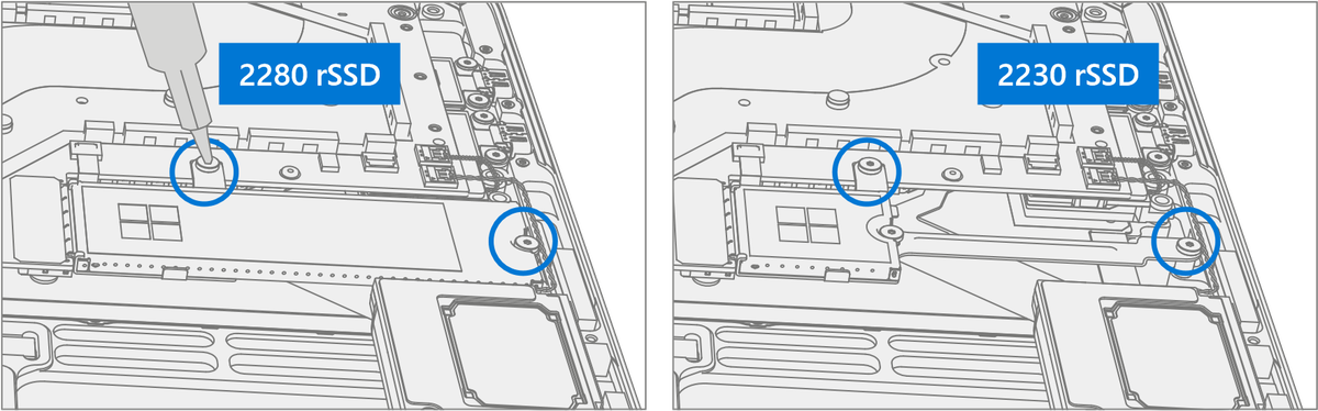
Remove rSSD – Removing the rSSD disconnects the battery from the rest of the electronic components in the unit. There are two sizes of rSSD. The longer 2280 and the shorter 2230 on a bracket.
Using a 3IP (Torx-Plus) driver remove the 2 screws securing the rSSD.

c. Remove Thermal Pad – Remove old rSSD thermal pad and clean residue with IPA.

Disconnect Battery Cable
Important
The battery cable connector doesn't detach in one single motion. Don't keep pulling vertically after the first “click”. Don't touch or press on the battery during connector removal.
a. Pull vertically on the battery cable labeled “Pull” until the snaps on both sides of the connector are released (the connector will still be retained in the plug).

b. Using the “Pull” tab, slide the connector carefully towards the battery to release the latches and remove the cable. Avoid impacting or poking the battery during this process.

Important
Place the Chassis somewhere where the battery can't accidentally be contacted or damaged. The Chassis is preferably stored vertically to prevent anything from being placed on top of the battery.
Important
When replacing the battery dispose of the old battery according to local laws.
Clean PSA Residue From Cosmetic Plate
- Place the top lip of chassis over the edge of the Keyboard Assembly.
- Remove any adhesive tape remnants from the cosmetic plate.
- Clean the bonding surfaces of the pen charger cover, the hinges
on the keyboard, and the chassis with 70% Isopropyl Alcohol.
Apply Citrus IPA cleaner (example Goo Gone) to the cosmetic plate residue and let it sit for 5 minutes.
Scrub the surface to remove as much of the PSA residue as possible. iii. Clean off any oil and glue residue with 70% Isopropyl Alcohol. iv. Repeat steps ‘1’ through ‘3’ as necessary until there's no residue remaining.
Clean remaining oil from all surrounding areas with 70% Isopropyl Alcohol.
Important
Be careful not to apply too much force when cleaning the PSA residue. Excessive force can damage and/or warp the cosmetic plate. If necessary, rotate the edges of the chassis to rest on the keyboard lip.

Remove Pen Shim (Optional) – If pen shim was damaged during the removal of the cosmetic plate it must be replaced. On the Keyboard Assembly place the pointed end of a spudger underneath the right side of the shim to pry it up and remove it. Clean any residual PSA with IPA.

Device Serial Number Notation – If Chassis + Battery is being replaced, the serial number of the device must be noted on the new device. The serial number for this device model is located on its original cover. Refer to Device Identity Information (page 6). To keep track of the device’s serial number, record it using waterproof ink on a sticker or label and apply the sticker or label to an easily accessible area on the device exterior. The serial number can't be added permanently to a replacement part. Microsoft might have provided a label for this use in the replacement part’s packaging.
Procedure - Installation (Chassis + Battery)
Pre-installation Device Inspection – Check Chassis (both sides) and device enclosure for any loose articles that might be present.
- Check and remove any foreign objects that the magnets might have attracted. Refer to the circled Magnetized areas pictured.
- Pay special attention to the magnetized area around the bottom of the trackpad.
- Verify all removed screws are accounted for and haven't been misplaced in the device.
- Loose screws should never be stored on the magnetic areas of the C cover.
Apply PSA to Cosmetic Plate – Apply PSA to the cosmetic plate in the locations shown. After PSA is applied, pinch the PSA and the cosmetic plate together to ensure proper adhesion.
Important
The notches on the upper PSA’s face towards each other. Don't remove the liners from the PSA strips.

Install Pen Shim (Optional) – If pen shim was damaged during the removal of the cosmetic plate or separated from the pen charging board underneath, place the new pen shim in Keyboard Assembly, being sure to align holes in the shim with the screws and ensuring shim doesn't overlap the lip of the Keyboard Assembly.

Position the Chassis – Place the Chassis above the device as pictured. The bottom of the Chassis should be on the table with the battery facing up.

Connect Battery Cable
Angle the tip of the connector up and vertically insert the cable side of the connector into the receptacle on the battery. Slightly pull back on the connector to make sure that the hook is engaged as shown.

Press down on the tip of the connector on left and right sides. A click should be heard and felt on each side

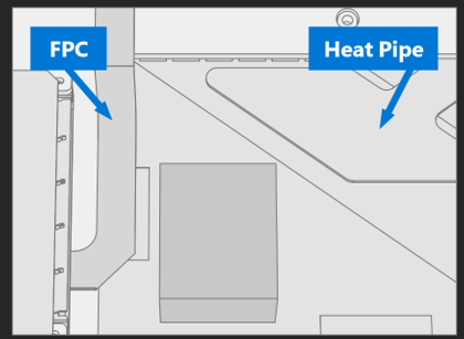
Replace Thermal Pad – Place new rSSD thermal pad in same approximate location.
Important
Thermal pad shouldn't touch the FPC to the left or heat pipe to the right.
Install rSSD – Insert the connector end of the rSSD into the rSSD connector on the motherboard at ~15-degree angle.

Install new rSSD screws – Using a 3IP (Torx-Plus) driver install 2 new rSSD Screws (M1167371). Turn all screws until snug and seated, and then turn another 45 degrees (1/8 turn) or until fully fastened.
Rotate the Chassis – Visually inspect the magnetized and Keyboard areas as noted in step 1. Rotate the Chassis about the hinge to prevent the battery cable from pulling on the battery connector. Set the Chassis down on the device.
Warning
Check to ensure that no loose articles are on the back cover or remain inside the device before reassembling it.

New Battery Charging – New batteries are shipped and stored at low states of charge in compliance with shipping regulations. They should be charged to at least 50%. This step takes between 20 minutes and 1 hour and is needed to validate full functionality of the new battery. Carefully place device right-side up. Open device, connect the power supply, and power it on.
New Battery Authentication – New batteries require authentication. After charging the new battery to at least 50%. Connect the SDT USB drive. Run the SDT battery repair validation to ensure all features and functions operate as expected. Power off at completion of tests. Remove SDT USB drive and power supply. If no further repairs are required proceed to final steps.
Original Battery Verify Device Functions – Carefully place device right-side up. Open device and connect the SDT USB drive, and power supply. Power on device then Run SDT to ensure all features and functions operate as expected. Power off at completion of tests. Remove SDT USB drive and power supply. If no further repairs are required proceed to final steps.
Install Chassis
- Remove the 3 clear liners on the cosmetic plate adhesive applied in step 2.
- Place the chassis on the Keyboard Assembly, ensuring that the cosmetic plate has an even lip around the circumference of the chassis and doesn't overhang the Keyboard Assembly. Verify the cosmetic plate doesn't overlap the Keyboard lip or display module and has equal gap concentricity around the corners.
- Use a 0.4-mm thickness gauge to check all edges of the cosmetic plate. The gauge shouldn't easily fit in any gaps between the cosmetic plate and device.
Warning
Alignment failures result in the need for a new cosmetic plate.

Install New Chassis Screws – Close device and carefully place it bottom-side up. Using a 3IP (Torx-Plus) driver install 7 new Chassis Screws (M1167779) in the foot wells. Turn all screws until snug and seated, and then turn another 45 degrees (1/8 turn) or until fully fastened.

Replace Cosmetic Plate (Optional) – If cosmetic plate was damaged during repair it must be replaced. Follow steps for Procedure – Installation (Cosmetic Plate).
Install Feet – Follow steps for Procedure – Installation (Feet).
rSSD Replacement Process
Preliminary Requirements
Important
Be sure to follow all special (bolded) notes of caution within each process section.
Required Tools and Components
All tools required for repair are listed under Service Tools and Jigs
All parts required for this repair will be provided in the CRU kit being purchased. CRU kits are listed on the Illustrated Parts List.
Important
Feet replacements must be ordered for each repair.
Prerequisite Steps
- Power off device – Ensure device is powered off by fully discharging the battery. Refer to Repair-Specific Precautions and Warnings section for details. Ensure device is disconnected from a power supply and all cables and drives are removed.
- ESD Prevention – Check to make sure that general guidelines and ESD Prevention steps are followed before opening device. Refer to ESD Prevention section for details.
- Position device – Place device onto a clean surface free of debris with the bottom facing up.
- Remove Feet – Refer to Procedure – Removal (Feet).
- Remove Chassis + Battery – Refer to Procedure – Removal (Chassis + Battery).
Procedure - Removal (rSSD)
Remove rSSD – rSSD removal disconnects the battery from the device. There are two sizes of rSSD. The longer 2280 and the shorter 2230 on a bracket.
- Using a 3IP (Torx-Plus) driver remove the 2 screws securing the rSSD.

Remove 2230 rSSD from bracket – Using a 3IP (Torx-Plus) driver remove the screw securing the 2230 rSSD to the bracket and then remove the rSSD.

Important
The 2230 rSSD bracket is reused when installing a new 2230 rSSD.
Remove Thermal Pad – Remove the old rSSD thermal pad and clean any residue with IPA.

Procedure - Installation (rSSD)
Install new 2230 rSSD to bracket – Using a 3IP (Torx-Plus) driver install a new 2230 rSSD to the bracket with a rSSD Screw (M1167371). Turn the screw until snug and seated, and then turn another 45 degrees (1/8 turn) or until it's fully fastened.

Replace Thermal Pad – Place new rSSD thermal pad in same approximate location.
Important
Thermal pad shouldn't touch the FPC to the left or the heat pipe to the right.

Insert rSSD – Insert the connector end of the rSSD into the receptacle on the motherboard at ~15-degree angle from horizontal.
Install new rSSD screws – Using a 3IP (Torx-Plus) driver install 2 new rSSD Screws (M1167371). Turn all screws until snug and seated, and then turn another 45 degrees (1/8 turn) or until fully fastened.

Install Battery – Follow steps for Procedure – Installation (Chassis + Battery) steps 4 through 8.
Important
During this installation only install rSSD and Chassis. Don't install Chassis screws and Cosmetic Plate.
Power On Device – Carefully place device top side up. Connect device to power supply, open display, and power on.
Imaging – Image the new rSSD by using a BMR Imaging USB drive specific to the device model.
Important
Refer to Surface imaging process - Surface Imaging Tools
Run SDT – Run SDT to ensure all device features and functions operate as expected.
Install Chassis – Follow steps for Procedure – Installation (Chassis + Battery).
Install Cosmetic Plate (Optional) – If cosmetic plate was damaged during repair it must be replaced. Follow steps for Procedure – Installation (Cosmetic Plate).
Install Feet – Follow steps for Procedure – Installation (Feet).
Display Replacement Process
Preliminary Requirements
Important
Be sure to follow all special (bolded) notes of caution within each process section.
Required Tools and Components
- All tools required for repair are listed under Service Tools and Jigs
- All parts required for this repair will be provided in the CRU kit being purchased. CRU kits are listed on the Illustrated Parts List.
Important
Feet replacements must be ordered for each repair.
Prerequisite Steps
Prep Device – Device must be set in TDM Replacement Mode prior to removing a faulty Display. This isn't required if the original Display will be reinstalled.
Connect software tools USB drive with SDT to USBconnector on device under repair.
Connect power supply to device.
Power on device – Depress the power button on the side of the device.
Run software tool – At the device OS, use Windows Explorer, navigate to USB drive and run:
SDT – Select Repair setup and validation. Run the Touch Display Setup. At the end of the tool process device will power down.
Warning
This step must be carried out on the device successfully before removal of a faulty Display
Power off device – Ensure device is powered off by fully discharging the battery. Refer to Repair-Specific Precautions and Warnings section for details. Ensure device is disconnected from a power supply and all cables and drives are removed.
ESD Prevention – Check to make sure that general guidelines and ESD Prevention steps are followed before opening device. Refer to ESD Prevention section for details.
Position device – Place device onto a clean surface free of debris with the bottom facing up.
Remove Feet – Refer to Procedure – Removal (Feet).
Remove Chassis + Battery – Refer to Procedure – Removal (Chassis + Battery).
Procedure - Removal (Display)
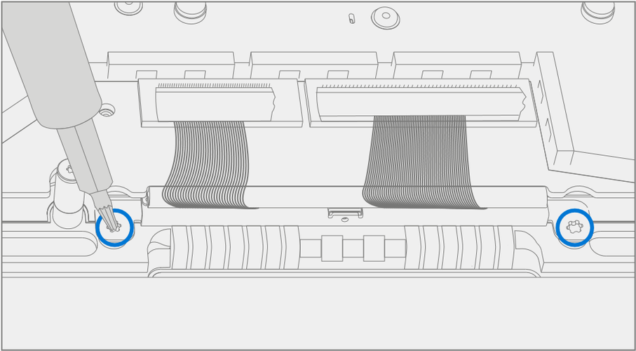
Remove 2 Cable Tensioners
Using a 3IP (Torx-Plus) driver remove the 2 screws from each of the cable tensioners.
Carefully lift the edge of the cable tensioners to remove them from the screw posts. Slide the cable tensioners out.
Disconnect 4 Display Cables – Use plastic tool to unlatch the connectors on the 4 display cables and carefully remove the cables from the PCBA connectors.
Important
The nearby foams are delicate. Take care not the damage or remove them.

Loosen Display hinge screws – Using a 6IP (Torx-Plus) driver loosen the 8 hinge screws by (1/8 turn) of a turn.

Position Display – Open the display to 90 degrees. Place the backside of the display module on the ESD safe workbench with the keyboard facing up.

Remove Left Hinge Screws – Using a 6IP (Torx-Plus) driver remove the 4 screws on the left hinge. Apply a 1-inch light duty spring clamp to the left hinge to hold it in place against the C-Cover.

Remove Right Hinge Screws – Using a 6IP (Torx-Plus) driver remove the 4 screws on the right hinge.

Remove display module from Keyboard – While holding the Keyboard with one hand carefully lift the keyboard from the display assembly.

Procedure - Installation (Display)
Remove Old Display Cable Foam – Display cable foam strips on the Keyboard are replaced before installation of the Display.

Remove left and right foam – Using a plastic tool remove the display cable foam from the left and right sides of the Keyboard.

Cleaning – Remove any adhesive tape remnants from the Keyboard and clean off any glue residue with 70% or greater Isopropyl Alcohol.

Install New Display Cable Foam – Remove the liner from the display cable foam. Align the display cable foam adhesive side down onto the Keyboard over the silver surface. Press down on the foam for 30 seconds. Repeat this for each side of the Keyboard.

Position Keyboard – Place the backside of the display on the ESD safe workbench with the hinges set at 90 degrees. Apply a 1-inch light duty spring clamp to the left hinge.
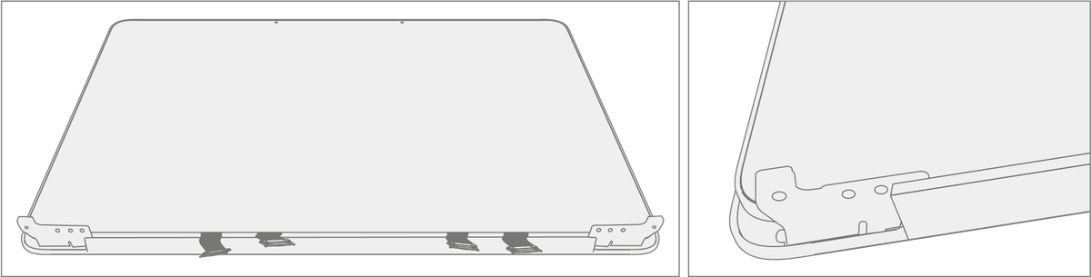
Install display module onto Keyboard – While holding the Keyboard with one hand. Carefully align the hinges into the pockets on the Keyboard.
Important
Ensure the Keyboard doesn't impact the display and that all display cables aren't pinched under the motherboard or display.

Pre-fasten right hinge screws – Assemble 4 new Hinge Screws (M1150078) in the right-side hinge and tighten until snug.

Pre-fasten left hinge screws – Remove the 1-inch light duty clamp form the left hinge. Assemble 4 new Hing Screws (M1150078) in the left side hinge and tighten until snug.
Hinge alignment
Close the device.
Loosen all 8 Hinge Screws 90 degrees (¼ turn).
Adjust the alignment until the back edge is flush across the hinge and Keyboard surfaces.

e. Tighten 1 screw on each hinge until snug then an additional 90 degrees and recheck alignment and 0.2mm gaps. 1. Repeat steps d and e on each of the 8 hinge screws.
Important
Placing a 0.25-mm plastic thickness gauge in the smaller of the 2 hinge gaps during step “e.” will aid in achieving a 0.2-mm gap after tightening.
Connect 4 Display Cables – Carefully connect the 4 display cables into the PCBA connectors. Ensure the connections are fully seated and the locking buckles are engaged.

Install 2 Cable Tensioners
Use the cable tensioners to gently push all 4 display cables so that they loop under the motherboard. Slide the cable tensioners in horizontally until the holes fit over the posts with the screw holes.

Ensure that the cables route over the plastic guide along the edge of the motherboard.

Using a 3IP (Torx-Plus) driver install the 2 new Tensioner Screws (M1177566) in each cable tensioner. Turn each screw until snug and seated, and then turn another 45 degrees (1/8 turn) or until screws are fully fastened.
Using a pair of tweezers apply foam to the connector cable in area shown.

Install Battery – Follow steps for Procedure - Installation (Chassis + Battery) steps 4 through 8.
Important
During this installation only install rSSD and Chassis. Don't install Chassis screws and Cosmetic Plate.
Power On Device – Carefully place device top side up. Connect device to power supply, open display, and power on.
New Display TDM Calibration – On installation of a new Display TDM device final calibration relies on the successful completion of the TDM Replacement Mode. TDM calibration isn't required when installing the originally removed Display.
- Connect software tools USB drive with SDT to USB connector on device under repair.
Run software tool – At the device OS, use Windows Explorer, navigate to USB drive and run:
SDT – Select Repair setup and validation. Run the Touch Display Calibration. Accept the restart prompt at the end of the tool process.
Important
This step must be carried out on the device successfully on installation of a new Display.
Run SDT – Run SDT to ensure all device features and functions operate as expected.
Install Chassis – Follow steps for Procedure – Installation (Chassis + Battery).
Install Cosmetic Plate (Optional) – If cosmetic plate was damaged during repair it must be replaced. Follow steps for Procedure – Installation (Cosmetic Plate).
Install Feet – Follow steps for Procedure – Installation (Feet).
Surflink Port Replacement Process
Preliminary Requirements
Important
Be sure to follow all special (bolded) notes of caution within each process section.
Required Tools and Components
- All tools required for repair are listed under Service Tools and Jigs
- All parts required for this repair will be provided in the CRU kit being purchased. CRU kits are listed on the Illustrated Parts List.
Important
Feet replacements must be ordered for each repair.
Prerequisite Steps
- Power off device – Ensure device is powered off by fully discharging the battery. Refer to Repair-Specific Precautions and Warnings section for details. Ensure device is disconnected from a power supply and all cables and drives are removed.
- ESD Prevention – Check to make sure that general guidelines and ESD Prevention steps are followed before opening device. Refer to ESD Prevention section for details.
- Position device – Place device onto a clean surface free of debris with the bottom facing up.
- Remove Feet – Refer to Procedure – Removal (Feet).
- Remove Chassis + Battery – Refer to Procedure – Removal (Chassis + Battery).
Procedure - Removal (Surflink Port)
Remove Left I/O Bracket – Using a 3IP (Torx-Plus) driver remove the 3 screws securing the left I/O Bracket to the Keyboard. Remove the Left I/O Bracket.

Remove Surflink Bracket – Using a 3IP (Torx-Plus) driver remove the 2 screws securing the Surflink Bracket to the PCBA. Remove the cable retainer.

Remove Surflink Port Screws – Using a 3IP (Torx-Plus) driver remove the 2 screws securing the Surflink Port to the Keyboard.
Important
Take care not to touch the Surflink FPCs with a driver. FPCs are delicate and can be easily damaged during removal/installation.

Disconnect Surflink FPCs – Using a plastic tool disconnect the Surflink FPCs from the PCBA.

Remove Surflink Port – Remove the Surflink Port from the Keyboard.

Procedure - Installation (Surflink Port)
Install Surflink Port – Place the Surflink Port into the Keyboard. Ensure the Keyboard posts nest into the Surflink Port slots.
Important
Take care not to touch the Surflink FPCs with a driver. FPCs are delicate and can be easily damaged during removal/installation.

Connect Surflink FPCs – Align the FPC’s connectors to the PCBA and press down.

Install new Surflink Port screws – Using a 3IP (Torx-Plus) driver install 2 new Surflink Screws (M1149393). Turn all screws until snug and seated, and then turn another 45 degrees (1/8 turn) or until fully fastened.
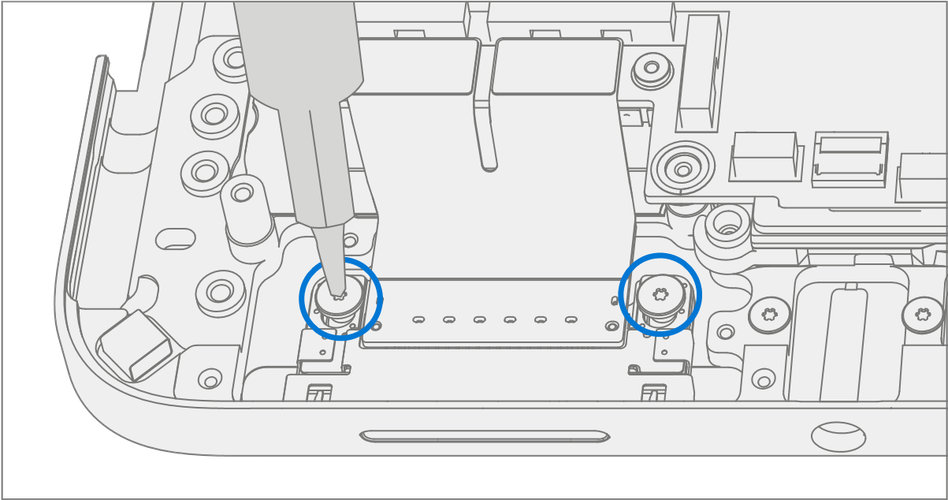
Install Surflink Bracket – Place the bracket over the Surflink FPCs. Using a 3IP (Torx-Plus) driver install 2 new Surflink Screws (M1149393). Turn all screws until snug and seated, and then turn another 45 degrees (1/8 turn) or until fully fastened.

Install Left I/O Bracket – Place the left I/O bracket onto the Keyboard. Using a 3IP (Torx-Plus) driver install 3 new Left I/O Bracket Screws (M1109237). Turn all screws until snug and seated, and then turn another 45 degrees (1/8 turn) or until fully fastened.

Install Battery – Follow steps for Procedure – Installation (Chassis + Battery) steps 4 through 8.
Important
During this installation only install rSSD and Chassis. Don't install Chassis screws and Cosmetic Plate.
Power On Device – Carefully place device top side up. Connect device to power supply, open display, and power on.
Run SDT – Run SDT to ensure all device features and functions operate as expected.
Install Chassis – Follow steps for Procedure – Installation (Chassis + Battery).
Install Cosmetic Plate (Optional) – If cosmetic plate was damaged during repair it must be replaced. Follow steps for Procedure – Installation (Cosmetic Plate).
Install Feet – Follow steps for Procedure – Installation (Feet).
Audio Jack Replacement Process
Preliminary Requirements
Important
Be sure to follow all special (bolded) notes of caution within each process section.
Required Tools and Components
- All tools required for repair are listed under Service Tools and Jigs
- All parts required for this repair will be provided in the CRU kit being purchased. CRU kits are listed on the Illustrated Parts List.
Important
Feet replacements must be ordered for each repair.
Prerequisite Steps
- Power off device – Ensure device is powered off by fully discharging the battery. Refer to Repair-Specific Precautions and Warnings section for details. Ensure device is disconnected from a power supply and all cables and drives are removed.
- ESD Prevention – Check to make sure that general guidelines and ESD Prevention steps are followed before opening device. Refer to ESD Prevention section for details.
- Position device – Place device onto a clean surface free of debris with the bottom facing up.
- Remove Feet – Refer to Procedure – Removal (Feet).
- Remove Chassis + Battery – Refer to Procedure – Removal (Chassis + Battery).
Procedure - Removal (Audio Jack)
Remove Left I/O Bracket – Using a 3IP (Torx-Plus) driver remove the 3 screws securing the left I/O Bracket to the Keyboard. Remove the Left I/O Bracket.

Remove Audio Jack Screws – Using a 3IP (Torx-Plus) driver remove the 2 screws securing the audio jack to the Keyboard.

Disconnect Audio Jack FPC – Release the lock on the Audio Jack FPC connector. Remove the Audio Jack FPC from the PCBA connector.

Remove Audio Jack – Remove the audio jack from the Keyboard by pulling up on the side with the FPC. Carefully move the Audio Jack from side to side during removal.

Procedure - Installation (Audio Jack)
Install Audio Jack – Place the open end of the audio jack into the hole in the Keyboard. Carefully move the Audio Jack from side to side during installation.

Connect Audio Jack FPC – Ensure the lock is released on the Audio Jack FPC connector. Install the Audio Jack FPC into the PCBA connector. Secure the connector lock.

Install New Audio Jack Screws – Using a 3IP (Torx-Plus) driver install 2 new Audio Jack Screws (M1168360). Turn all screws until snug and seated, and then turn another 45 degrees (1/8 turn) or until fully fastened.
Install Left I/O Bracket – Place the left I/O bracket onto the Keyboard. Using a 3IP (Torx-Plus) driver install 3 new Left I/O Bracket Screws (M1109237). Turn all screws until snug and seated, and then turn another 45 degrees (1/8 turn) or until fully fastened.

Install Battery – Follow steps for Procedure – Installation (Chassis + Battery) steps 4 through 8.
Important
During this installation only install rSSD and Chassis. Don't install Chassis screws and Cosmetic Plate.
Power On Device – Carefully place device top side up. Connect device to power supply, open display, and power on.
Run SDT – Run SDT to ensure all device features and functions operate as expected.
Install Chassis – Follow steps for Procedure – Installation (Chassis + Battery).
Install Cosmetic Plate (Optional) – If cosmetic plate was damaged during repair it must be replaced. Follow steps for Procedure – Installation (Cosmetic Plate).
Install Feet – Follow steps for Procedure – Installation (Feet).
USB-A + C Replacement Process
Preliminary Requirements
Important
Be sure to follow all special (bolded) notes of caution within each process section.
Required Tools and Components
- All tools required for repair are listed under Service Tools and Jigs
- All parts required for this repair will be provided in the CRU kit being purchased. CRU kits are listed on the Illustrated Parts List.
Important
Feet replacements must be ordered for each repair.
Prerequisite Steps
- Power off device – Ensure device is powered off by fully discharging the battery. Refer to Repair-Specific Precautions and Warnings section for details. Ensure device is disconnected from a power supply and all cables and drives are removed.
- ESD Prevention – Check to make sure that general guidelines and ESD Prevention steps are followed before opening device. Refer to ESD Prevention section for details.
- Position device – Place device onto a clean surface free of debris with the bottom facing up.
- Remove Feet – Refer to Procedure – Removal (Feet).
- Remove Chassis + Battery – Refer to Procedure – Removal (Chassis + Battery).
Procedure - Removal (USB-A + C)
Remove Right I/O Bracket – Using a 3IP (Torx-Plus) driver remove the 4 screws securing the Right I/O Bracket to the chassis. Remove the Right I/O Bracket.

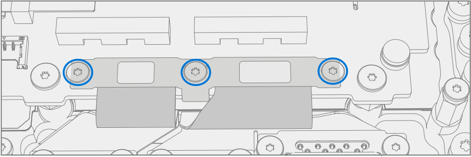
Remove USB Bracket– Using a 3IP (Torx-Plus) driver remove the 3 screws securing the USB Bracket to the motherboard.

Remove Right USB FPC – Using a plastic spudger disconnect the right USB FPC from the motherboard.
Remove USB-A + C Connector – Using a 3IP (Torx-Plus) driver remove the right 4 screws securing the USB-A + C Ports to the chassis and remove.
Important
Take care not to touch USB FPCs with driver. FPCs are delicate and can be easily damaged during removal installation.

Procedure - Installation (USB-A + C)
Install USB-A +C Connector – Place the USB port into the chassis, aligning holes with posts on the chassis. Using a 3IP (Torx-Plus) driver install the 4 USB Port Screws (M1149389). Turn all screws until snug and seated, and then turn another 45 degrees (1/8 turn) or until fully fastened.
Install Right USB FPC – Align the right USB FPC to the motherboard and press down firmly. A small click might be heard.
Important
The connectors on the motherboard are fragile. Ensure proper alignment before pressing down the connectors. Damage to the connectors on the Motherboard require replacement of the Motherboard. The connectors edge should be aligned with the mark line on the Motherboard.

Install USB Bracket – Install the USB bracket using 3IP (Torx-Plus) driver and 3 USB Bracket Screws (M1167780). Turn all screws until snug and seated, and then turn another 45 degrees (1/8 turn) or until fully fastened.

Install Right I/O Bracket – Install Right I/O bracket using a 3IP (Torx-Plus) driver and 4 Right I/O Bracket Screws (M1109237). Turn all screws until snug and seated, and then turn another 45 degrees (1/8 turn) or until fully fastened.

Install Battery – Follow steps for Procedure – Installation (Chassis + Battery) steps 4 through 8.
Important
During this installation only install rSSD and Chassis. Don't install Chassis screws and Cosmetic Plate.
Power On Device – Carefully place device top side up. Connect device to power supply, open display, and power on.
Run SDT – Run SDT to ensure all device features and functions operate as expected.
Install Chassis – Follow steps for Procedure – Installation (Chassis + Battery).
Install Cosmetic Plate (Optional) – If cosmetic plate was damaged during repair it must be replaced. Follow steps for Procedure – Installation (Cosmetic Plate).
Install Feet – Follow steps for Procedure – Installation (Feet).
USB-C Replacement Process
Preliminary Requirements
Important
Be sure to follow all special (bolded) notes of caution within each process section.
Required Tools and Components
- All tools required for repair are listed under Service Tools and Jigs
- All parts required for this repair will be provided in the CRU kit being purchased. CRU kits are listed on the Illustrated Parts List.
Important
Feet replacements must be ordered for each repair.
Prerequisite Steps
- Power off device – Ensure device is powered off by fully discharging the battery. Refer to Repair-Specific Precautions and Warnings section for details. Ensure device is disconnected from a power supply and all cables and drives are removed.
- ESD Prevention – Check to make sure that general guidelines and ESD Prevention steps are followed before opening device. Refer to ESD Prevention section for details.
- Position device – Place device onto a clean surface free of debris with the bottom facing up.
- Remove Feet – Refer to Procedure – Removal (Feet).
- Remove Chassis + Battery – Refer to Procedure – Removal (Chassis + Battery).
Procedure - Removal (USB-C)
Remove Right I/O Bracket – Using a 3IP (Torx-Plus) driver remove the 4 screws securing the Right I/O Bracket to the chassis. Remove the Right I/O Bracket.
Remove USB Bracket – Using a 3IP (Torx-Plus) driver remove the 3 screws securing the USB Bracket to the motherboard.
Remove Left USB FPC – Using a plastic spudger disconnect the left USB FPC from the motherboard.

Remove USB Connectors – Using a 3IP (Torx-Plus) driver remove the 2 screws securing the USB-C Port to the chassis and remove.
Important
The connectors on the motherboard are fragile. Ensure proper alignment before pressing down the connectors. Damage to the connectors on the Motherboard require replacement of the Motherboard. The connectors edge should be aligned with the mark line on the Motherboard.

Procedure - Installation (USB-C)
Install USB-C Connector – Place USB-C port into the chassis, aligning holes with posts on the chassis. Using a 3IP (Torx-Plus) driver install the 2 USB Port Screws (M1149389). Turn all screws until snug and seated, and then turn another 45 degrees (1/8 turn) or until fully fastened.
Install Left USB FPC – Connect the USB FPCs to the motherboard.
Important
The connectors on the motherboard are fragile. Ensure proper alignment before pressing down the connectors. Damage to the connectors on the Motherboard require replacement of the Motherboard. The connectors edge should be aligned with the mark line on the Motherboard.
Install USB Bracket – Install the USB bracket using 3IP (Torx-Plus) driver and 3 USB Bracket Screws (M1167780). Turn all screws until snug and seated, and then turn another 45 degrees (1/8 turn) or until fully fastened.
Install Right I/O Bracket – Install Right I/O bracket using a 3IP (Torx-Plus) driver and 4 Right I/O Bracket Screws (M1109237). Turn all screws until snug and seated, and then turn another 45 degrees (1/8 turn) or until fully fastened.
Install Battery – Follow steps for Procedure – Installation (Chassis + Battery) steps 4 through 8.
Important
During this installation only install rSSD and Chassis. Don't install Chassis screws and Cosmetic Plate.
Power On Device – Carefully place device top side up. Connect device to power supply, open display, and power on.
Run SDT – Run SDT to ensure all device features and functions operate as expected.
Install Chassis – Follow steps for Procedure – Installation (Chassis + Battery).
Install Cosmetic Plate (Optional) – If cosmetic plate was damaged during repair it must be replaced. Follow steps for Procedure – Installation (Cosmetic Plate).
Install Feet – Follow steps for Procedure – Installation (Feet).
Micro SD Slot Replacement Process
Preliminary Requirements
Important
Be sure to follow all special (bolded) notes of caution within each process section.
Required Tools and Components
- All tools required for repair are listed under Service Tools and Jigs
- All parts required for this repair will be provided in the CRU kit being purchased. CRU kits are listed on the Illustrated Parts List.
Important
Feet replacements must be ordered for each repair.
Prerequisite Steps
- Power off device – Ensure device is powered off by fully discharging the battery. Refer to Repair-Specific Precautions and Warnings section for details. Ensure device is disconnected from a power supply and all cables and drives are removed.
- ESD Prevention – Check to make sure that general guidelines and ESD Prevention steps are followed before opening device. Refer to ESD Prevention section for details.
- Position device – Place device onto a clean surface free of debris with the bottom facing up.
- Remove Feet – Refer to Procedure – Removal (Feet).
- Remove Chassis + Battery – Refer to Procedure – Removal (Chassis + Battery).
Procedure - Removal (Micro SD Slot)
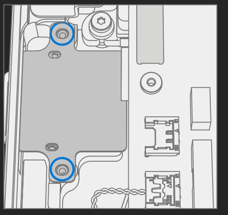
Remove Bracket – Use a 3IP (Torx-Plus) driver to remove the 2 Micro SD Bracket Screws and remove the bracket.

Disconnect Left Tweeter – Disconnect the left tweeter from the motherboard by lifting straight up. Move the connector to the side.
Important
Tweeter cables are fragile. Take care not to damage them.

Disconnect Micro SD FPC – Use a plastic spudger to disconnect the Micro SD FPC from the motherboard.

Remove Micro SD Slot – Using a 3IP (Torx-Plus) driver remove the 2 SD Slot Screws from the chassis. Lift Micro SD Slot to remove.

Procedure - Installation (Micro SD Slot)
Install Micro SD Slot – Place the Micro SD Slot into the Keyboard Assembly. Using a 3IP (Torx-Plus) driver install the 2 SD Slot Screws (M1149393). Turn all screws until snug and seated, and then turn another 45 degrees (1/8 turn) or until fully fastened.
Important
Pull the tweeter cable away from the Micro SD Slot before installation. Tweeter cable shouldn't be routed behind the Micro SD FPC.
Connect Micro SD FPC – Making sure tweeter connector is out of the way, align the Micro SD Slot connector with the motherboard and press in firmly. A small click might be heard.
Important
The connectors on the motherboard are fragile. Ensure proper alignment before pressing down the connectors. Damage to the connectors on the Motherboard require replacement of the Motherboard. The connectors edge should be aligned with the mark line on the Motherboard.

Connect Left Tweeter – Connect the left tweeter to the motherboard by aligning with connector and pressing down firmly.

Install Bracket – Place the Micro SD Bracket over the FPC. Using a 3IP (Torx-Plus) driver, install the 2 Micro SD Bracket Screws (M1156309). Turn all screws until snug and seated, and then turn another 45 degrees (1/8 turn) or until fully fastened.

Install Battery – Follow steps for Procedure – Installation (Chassis + Battery) steps 4 through 8.
Important
During this installation only install rSSD and Chassis. Don't install Chassis screws and Cosmetic Plate.
Power On Device – Carefully place device top side up. Connect device to power supply, open display, and power on.
Run SDT – Run SDT to ensure all device features and functions operate as expected.
Install Chassis – Follow steps for Procedure – Installation (Chassis + Battery).
Install Cosmetic Plate (Optional) – If cosmetic plate was damaged during repair it must be replaced. Follow steps for Procedure – Installation (Cosmetic Plate).
Install Feet – Follow steps for Procedure – Installation (Feet).
Motherboard Replacement Process
Preliminary Requirements
Important
Be sure to follow all special (bolded) notes of caution within each process section.
Important
If replacing both the Motherboard and Display, complete the Motherboard repair first and ensure functionality before beginning the Display replacement procedure. Failure to do so might result in Display functionality being impacted.
Required Tools and Components
- All tools required for repair are listed under Service Tools and Jigs
- All parts required for this repair will be provided in the CRU kit being purchased. CRU kits are listed on the Illustrated Parts List.
Important
Feet replacements must be ordered for each repair.
Prerequisite Steps
- Power off device – Ensure device is powered off by fully discharging the battery. Refer to Repair-Specific Precautions and Warnings section for details. Ensure device is disconnected from a power supply and all cables and drives are removed.
- ESD Prevention – Check to make sure that general guidelines and ESD Prevention steps are followed before opening device. Refer to ESD Prevention section for details.
- Position device – Place device onto a clean surface free of debris with the bottom facing up.
- Remove Feet – Refer to Procedure – Removal (Feet).
- Remove Chassis + Battery – Refer to Procedure – Removal (Chassis + Battery).
Procedure - Removal (Motherboard)
Disconnect 4 Display Cables – Use plastic tool to unlatch the connectors on the 4 display cables and carefully remove the cables from the PCBA connectors.
Important
The nearby foams are delicate. Take care not to damage or remove them.

Remove Surflink Bracket – Using a 3IP (Torx-Plus) driver remove the 2 screws securing the Surflink Bracket to the PCBA. Remove the bracket.

Disconnect Surflink FPCs – Using a plastic tool disconnect the Surflink FPCs from the PCBA.
Disconnect Audio Jack FPC – Release the lock on the Audio Jack FPC connector. Remove the Audio Jack FPC from the PCBA connector.

Disconnect 4 Speaker Cables – Using a plastic tool carefully release the 4 speaker connectors from the PCBA.

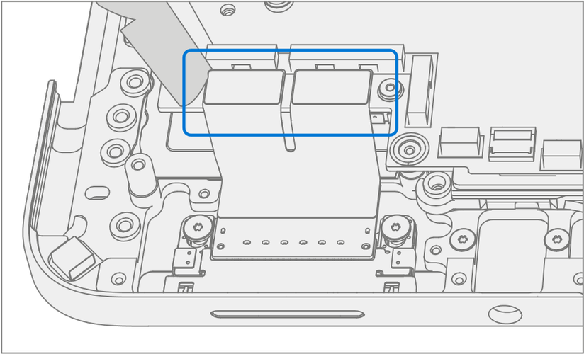
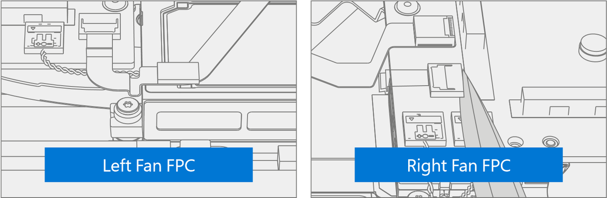
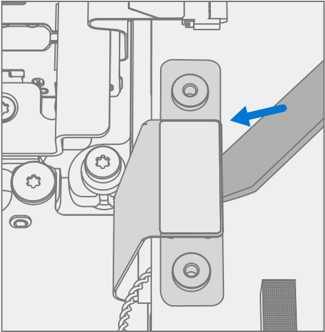
Disconnect Fan FPCs – Release the locks on the left and right Fan FPC connectors. Remove the left and right Fan FPCs from the PCBA connectors.
Disconnect Trackpad FPC – Release the lock on the Trackpad FPC connector. Remove the Trackpad FPC from the PCBA connector.

Disconnect Keyset FPC – Release the lock on the Keyset FPC connector. Remove the Keyset FPC from the PCBA connector.

Disconnect Keyset Backlight FPC – Release the lock on the Keyset Backlight FPC connector. Remove the Keyset Backlight FPC from the PCBA connector.

Disconnect Wireless Pen Charger FPC – Using a plastic tool carefully release the Wireless Pen Charger from the PCBA connector.

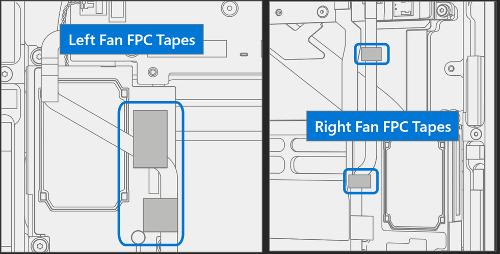
Remove Fan FPC Tapes – Carefully remove the 4 black tapes securing the fan FPCs. And 1 black tape securing the subwoofer.

Remove Speaker Tape – Remove the tape holding the subwoofer wire.

Remove Left and Right Speakers – Using a 3IP (Torx-Plus) driver remove the 3 screws securing the left speaker, and 3 screws securing the right speaker to the Keyboard. Remove the speakers.

Remove USB Bracket– Using a 3IP (Torx-Plus) driver remove the 3 screws securing the USB Bracket to the motherboard.

Remove USB FPC’s – Using a plastic spudger disconnect the two USB FPCs from the motherboard.

Remove Micro SD Slot Bracket – Use a 3IP (Torx-Plus) driver to remove the 2 Micro SD Bracket Screws and remove the bracket.

Disconnect Micro SD FPC – Use a plastic spudger to disconnect the Micro SD FPC from the motherboard.
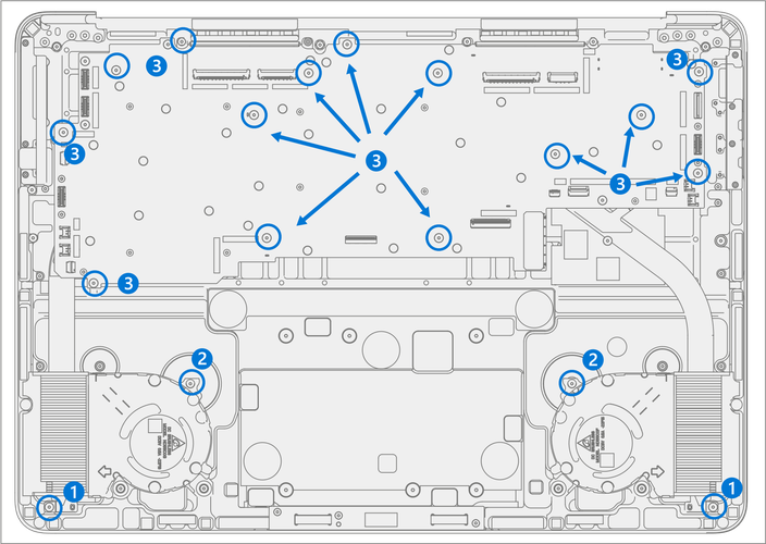
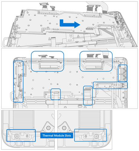
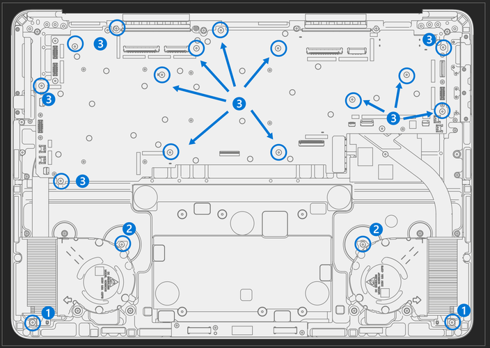
Remove Screws
Using a 3IP (Torx-Plus) driver remove the 2 screws, marked 1, securing the thermal module to the Keyboard.
Using a 3IP (Torx-Plus) driver remove the 2 screws, marked 2, securing the fans to the Keyboard.
Using a 3IP (Torx-Plus) driver remove the 14 screws, marked 3, securing the motherboard to the Keyboard.
Remove Fans – Remove the left and right fans from the chassis. Reserve the grommets under the fans for future installation.

Remove PCBA – Start by holding the Surflink and Micro SD Slot FPCs out of the way and slightly pick up the left side of the PCBA. Rotate the PCBA up and out. Ensure no FPCs or connectors catch on the motherboard.

Procedure - Installation (Motherboard)
Install PCBA – Install the right side of the PCBA down and into the Keyboard. Ensure no connectors or FPC’s catch on the motherboard or get pinched underneath. Lower the left side of the PCBA into the Keyboard while holding the Surflink and Micro SD Slot FPCs out of the way.
Important
Verify the 15 cables and FPCs aren't captured under the PCBA. The Fan and Wireless Pen Charger FPCs route over the thermal heat pipe. Ensure the thermal module slots align over the posts in the Keyboard.
Install Fans – Place 2 grommets on each post for the left and right-side fans as shown. Install fans, aligning holes with posts.

Install Screws – Turn all screws until snug and seated, and then turn another 45 degrees (1/8 turn) or until fully fastened.
Using a 3IP (Torx-Plus) driver install 2 new Thermal Module Screws (M1149393), marked 1.
Using a 3IP (Torx-Plus) driver install 2 new Fan Screws (M1007493), marked 2.
Using a 3IP (Torx-Plus) driver install 14 new Motherboard Screws (M1184901), marked 3.
Important
the screws are different lengths. Failure to install the correct screws could result in the screws coming loose over time resulting in internal damage to the device.
Install USB FPC’s – Connect the USB FPCs to the motherboard.
Important
The connectors on the motherboard are fragile. Ensure proper alignment before pressing down the connectors. Damage to the connectors on the motherboard requires a motherboard replacement. The connector edge should be aligned with the mark line on the motherboard.

Install USB Bracket– Install the USB bracket using 3IP (Torx-Plus) driver and 3 USB Bracket Screws (M1167780). Turn all screws until snug and seated, and then turn another 45 degrees (1/8 turn) or until fully fastened.

Connect Micro SD FPC – Making sure tweeter connector is out of the way, align the Micro SD Slot connector with the motherboard and press in firmly. A small click might be heard.
Important
The connectors on the motherboard are fragile. Ensure proper alignment before pressing down the connectors. Damage to the connectors on the motherboard requires a motherboard replacement.

Install Micro SD Slot Bracket – Place the Micro SD Bracket over the FPC. Using a 3IP (Torx-Plus) driver, install the 2 Micro SD Bracket Screws (M1156309). Turn all screws until snug and seated, and then turn another 45 degrees (1/8 turn) or until fully fastened.

Install Left and Right Speakers – Place the left and right speakers into the Keyboard. Using a 3IP (Torx-Plus) driver install 3 new Speaker Screws (M1202147) in the left speaker, and 3 new Speaker Screws (M1202147) in the right speaker. Turn all screws until snug and seated, and then turn another 45 degrees (1/8 turn) or until fully fastened.

Install Speaker Tape – Install the tape holding the subwoofer wire in area shown.

Connect 4 Speaker Cables – Align the left and right Speaker Cable connectors to the PCBA and press down. Ensure the cables don't overlap and are routed as pictured.

Connect Wireless Pen Charger FPC – Align the FPC’s connector to the PCBA and press down.

Connect Keyset Backlight FPC – Ensure the lock is released on the Keyset Backlight FPC connector. Install the Keyset Backlight FPC into the PCBA connector. Secure the connector lock.

Connect Keyset FPC – Ensure the lock is released on the Keyset FPC connector. Install the Keyset FPC into the PCBA connector. Secure the connector lock.

Connect Trackpad FPC – Ensure the lock is released on the Trackpad FPC connector. Install the Trackpad FPC into the PCBA connector. Secure the connector lock.

Connect Fan FPCs – Ensure the locks are released on the left and right Fan FPC connectors. Install the left and right Fan FPCs into the PCBA connectors. Secure the connector locks.

Install New Fan FPC Tapes – Refer to the picture for tape locations. Apply 2 black tapes to the left Fan FPC securing it to the left speaker. Apply 1 black tape on the right Fan FPC securing it to the right speaker. Apply 1 black tape on the right Fan FPC securing it to the Keyboard.
Important
Don't place tapes on the sliver metallic areas of the speaker housing.
Connect Audio Jack FPC – Ensure the lock is released on the Audio Jack FPC connector. Install the Audio Jack FPC into the PCBA connector. Secure the connector lock.

Connect Surflink FPCs – Align the FPC’s connectors to the PCBA and press down.

Install Surflink Bracket – Place the bracket over the Surflink FPCs. Using a 3IP (Torx-Plus) driver install 2 new Surflink Bracket Screws (M1149393). Turn all screws until snug and seated, and then turn another 45 degrees (1/8 turn) or until fully fastened.

Connect 4 Display Cables – Carefully connect the 4 display cables into the PCBA connectors. Ensure the connections are fully seated and the locking buckles are engaged.

- Ensure that the cables route over the plastic guide along the edge of the motherboard.

Install Battery – Follow steps for Procedure – Installation (Chassis + Battery) steps 4 through 7.
Important
During this installation only install rSSD and Chassis. Don't install Chassis screws and Cosmetic Plate.
Power On Device – Carefully place device top side up. Connect device to power supply, open display, and power on.
Complete Display Calibration
Connect software tools USB drive with SDT to USB connector on device under repair.
Run software tool – At the device OS, use Windows Explorer, navigate to USB drive, and run:
SDT – Select Repair setup and validation. Run the Touch Display Calibration. Accept the restart prompt at the end of the tool process.
Important
This step must be conducted on the device successfully on installation of a new motherboard to ensure proper display functionality.
New Battery Authentication – Ensure the battery reads as authenticated in the Battery Repair (Validation) workflow in SDT. If the battery shows as inauthentic run the SDT Battery Repair (Validation) workflow in its entirety.
• Connect the SDT Configuration USB drive.
• Run the SDT Battery Repair (Validation) to ensure the battery is properly authenticated and all features and functions operate as expected.
Important
Battery authentication requires a stable internet connection. If any battery steps fail retry with a new internet connection. If failures continue reach out to Microsoft Support.
Run SDT – Run SDT to ensure all device features and functions operate as expected.
Install Chassis – Follow steps for Procedure – Installation (Chassis + Battery).
Install Cosmetic Plate (Optional) – If cosmetic plate was damaged during repair it must be replaced. Follow steps for Procedure – Installation (Cosmetic Plate).
Install Feet – Follow steps for Procedure – Installation (Feet).
Keyboard Assembly Replacement Process
Preliminary Requirements
Important
Be sure to follow all special (bolded) notes of caution within each process section.
Required Tools and Components
- All tools required for repair are listed under Service Tools and Jigs
- All parts required for this repair will be provided in the CRU kit being purchased. CRU kits are listed on the Illustrated Parts List.
Important
Feet replacements must be ordered for each repair.
Prerequisite Steps
Power off device – Ensure device is powered off by fully discharging the battery. Refer to Repair-Specific Precautions and Warnings section for details. Ensure device is disconnected from a power supply and all cables and drives are removed.
ESD Prevention – Check to make sure that general guidelines and ESD Prevention steps are followed before opening device. Refer to ESD Prevention section for details.
Position device – Place device onto a clean surface free of debris with the bottom facing up.
Remove Feet – Refer to Procedure – Removal (Feet).
Remove Chassis + Battery – Refer to Procedure – Removal (Chassis + Battery).
Remove Display – Refer to Procedure – Removal (Display).
Important
The use of SDT TDM Replacement Mode is only required during Display replacements.
Remove Surflink Port – Refer to Procedure – Removal (Surflink).
Remove Audio Jack – Refer to Procedure – Removal (Audio Jack).
Remove USB-A+C Ports – Refer to Procedure – Removal (USB-A+C).
Remove USB-C Port – Refer to Procedure – Removal (USB-C).
Remove Micro SD Slot – Refer to Procedure – Removal (Micro SD Slot).
Remove Motherboard – Refer to Procedure – Removal (Motherboard).
Procedure - Removal (Keyboard Assembly)
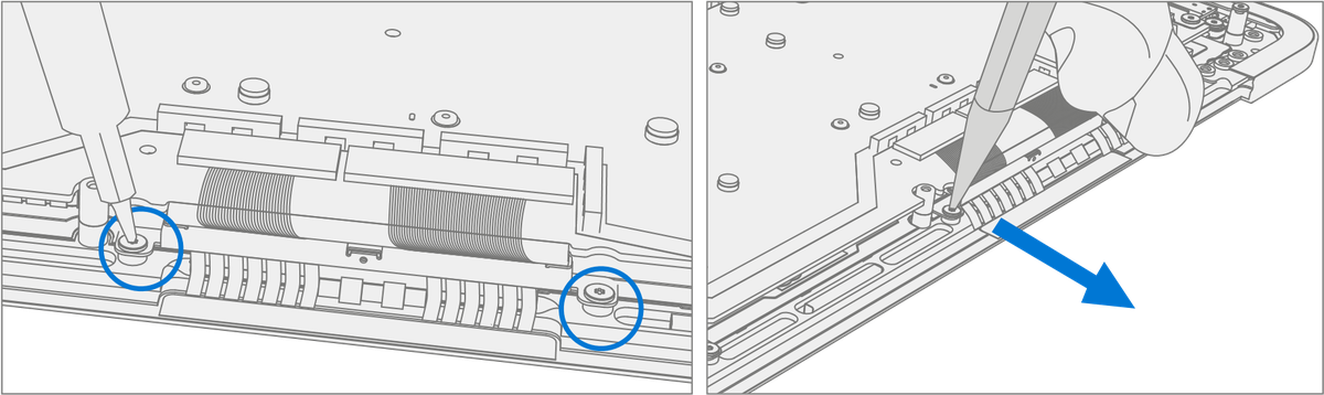
Remove Tweeters – Use a 3IP (Torx-Plus) driver to remove the 2 screws from each of the left and right tweeters. Remove the tweeters.

Procedure – Installation (Keyboard Assembly)
Install Tweeters – Install the previously removed right and left tweeters onto the new Keyboard. Using 3IP install 2 new Speaker Screws (M1202147) on each tweeter. Turn all screws until snug and seated, and then turn another 45 degrees (1/8 turn) or until fully fastened.

Install Motherboard – Follow steps for Procedure – Installation (Motherboard).
Install Micro SD Slot – Follow steps for Procedure – Installation (Micro SD Slot).
Install USB-A + C – Follow steps for Procedure – Installation (USB-A + C).
Install USB-C – Follow steps for Procedure – Installation (USB-C).
Install Audio Jack – Follow steps for Procedure – Installation (Audio Jack).
Install Surflink Port – Follow steps for Procedure – Installation (Surflink).
Install Display – Follow steps for Procedure – Installation (Display).
Install Battery – Follow steps for Procedure – Installation (Chassis + Battery) steps 4 through 8.
Important
During this installation only install rSSD and Chassis. Don't install Chassis screws and Cosmetic Plate.
Power On Device – Carefully place device top side up. Connect device to power supply, open display, and power on.
Run SDT – Run SDT to ensure all device features and functions operate as expected.
Install Chassis – Follow steps for Procedure – Installation (Chassis + Battery).
Install Cosmetic Plate (Optional) – If cosmetic plate was damaged during repair it must be replaced. Follow steps for Procedure – Installation (Cosmetic Plate).
Install Feet – Follow steps for Procedure – Installation (Feet).
Cosmetic Plate Replacement Process
Preliminary Requirements
Important
Be sure to follow all special (bolded) notes of caution within each process section.
Required Tools and Components
- All tools required for repair are listed under Service Tools and Jigs
- All parts required for this repair will be provided in the CRU kit being purchased. CRU kits are listed on the Illustrated Parts List.
Important
Feet replacements must be ordered for each repair.
Prerequisite Steps
- Power off device – Ensure device is powered off by fully discharging the battery. Refer to Repair-Specific Precautions and Warnings section for details. Ensure device is disconnected from a power supply and all cables and drives are removed.
- ESD Prevention – Check to make sure that general guidelines and ESD Prevention steps are followed before opening device. Refer to ESD Prevention section for details.
- Position device – Place device onto a clean surface free of debris with the bottom facing up.
Procedure - Removal (Cosmetic Plate)
Remove Cosmetic Plate
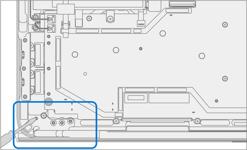
Starting at the rear hinge, use a spudger or plastic tweezers to lift up the end of the cosmetic plate.

Peel off the cosmetic plate.
Important
Pull the cosmetic plate away from the device at an angle to prevent scratching the Chassis.

Important
Along the front edge, pull the cosmetic plate in a tight ‘U’ shape to prevent the pen shim from lifting with the cosmetic plate. A replacement pen shim is included with the new Cosmetic Plate in situations where it's removed.
Cleaning
- Remove any adhesive tape remnants from the Chassis.
- Clean the bonding surfaces of the pen charger cover, the hinges
on the Keyboard, and the Chassis with 70% Isopropyl Alcohol.
- Apply Citrus IPA cleaner (example Goo Gone) to the cosmetic plate residue and let it sit for 5 minutes.
- Scrub the surface to remove as much of the PSA residue as possible. iii. Clean off any oil and glue residue with 70% Isopropyl Alcohol. iv. Repeat steps ‘1’ through ‘3’ as necessary until there's no residue remaining.
- Clean remaining oil from all surrounding areas with 70% Isopropyl Alcohol.
Procedure - Installation (Cosmetic Plate)
Important
Once removed, the cosmetic plate must be replaced with new a one.
Install Chassis – Follow steps for Procedure – Installation (Chassis + Battery).
Install New Cosmetic Plate
Place device onto a clean surface free of debris with the bottom facing up.
Remove the clear plastic adhesive sheet.
Remove the 3 clear liners on the cosmetic plate adhesive.
Place the cosmetic plate adhesive-side down so the open side of the ‘C’ shape matches up with the display module hinge.

Important
Look through the blue liner and adjust the cosmetic plate where necessary to ensure that gaps on the sides of the cosmetic plate are even and consistent.
Press lightly ensuring the entire cosmetic plate is fully down on the device.
Firmly press the cosmetic plate with your finger, going all the way around.
Remove the blue liner and run your finger over the cosmetic plate again to make sure that it's securely adhered.
Verify Alignment
- Use a 0.4-mm thickness gauge to check all edges of the cosmetic plate. The gauge shouldn't easily fit in any gaps between the cosmetic plate and device.
- Verify the cosmetic plate doesn't overlap the Keyboard lip or display module and has equal gap concentricity around the corners.
Important
Any alignment failures require installation of a new cosmetic plate.
