Note
Access to this page requires authorization. You can try signing in or changing directories.
Access to this page requires authorization. You can try changing directories.
Warning
Review the General Safety Precautions and Battery Safety guidelines in their entirety before proceeding with any repair steps.
Important
Read this Guide in its entirety before starting any repairs. If at any point you're unsure or uncomfortable about performing the repairs, as detailed in this Guide, DO NOT proceed. Contact Microsoft for more support options.
Warning
Failure to follow the instructions in this Guide, use of non-Microsoft (nongenuine), incompatible, or modified replacement parts, and/or failure to use proper tools could result in serious injury, death, and/or damage to the product or other property.
Prerequisite Steps
Steps outlined in this section should be conducted before starting any repair on a Surface device.
Power off device – Ensure the device is powered off completely and the battery has been fully discharged. Refer to the Repair-specific precautions and warnings section for guidelines. Once discharged, the device should be disconnected from all power sources.
ESD Prevention – Ensure ESD prevention steps and general guidelines are followed before opening the device. Refer to the ESD Prevention section for guidelines.
Position Device – To prevent damage to the device, ensure the device is placed on a clean surface free of debris.
Kickstand Replacement Process
Preliminary Requirements
Important
Be sure to follow all special (bolded) notes of caution within each process section.
Required Tools
- 3IP (Torx-plus) driver
- Loctite 7649
- Loctite 243
- Microfiber Cloth
Primary Components
- Kickstand (Refer to the Illustrated Service Parts List)
- 2 x Kickstand Screw (M1.6xL2.05/3IP)
- 13NL-5JN1901 for Platinum
- 13NL-5JN1B01 for Graphite
- 2 x Kickstand Screw (M1.6xL2.05/3IP)
Additional Components (Ordered Separately)
- N/A
Procedure - Removal (Kickstand)
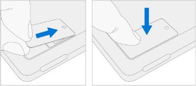
- Extend the kickstand to approximately 90-degrees.
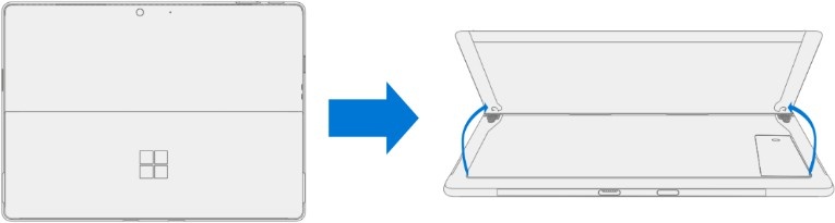
- Remove the hinge screws – Using your finger, hold the back of the kickstand behind the hinge. Using a 3IP (Torx-plus) driver, remove one screw from each hinge. Ensure the screws don't fall into the hinge opening.
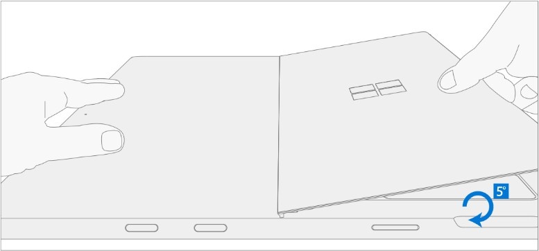
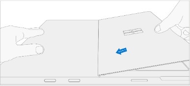
- Angle the Kickstand down – Firmly grip the hinges and the kickstand between your thumb and index fingers. Rotate the kickstand from 90 degrees to approximately 45 degrees.

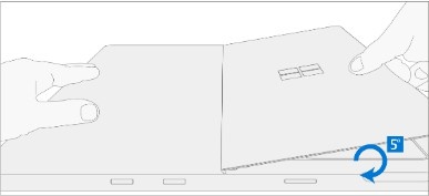
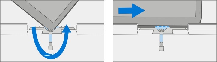
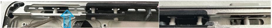
- Release the Kickstand threaded bosses – Place your fingers on the underside of the kickstand, and your thumb on the topside. Slightly rotate the kickstand on its axis as shown. The kickstand should rotate approximately 5 degrees to free the two threaded bosses of the kickstand from the recesses of the hinge.
- Remove the Kickstand – Using the palm of your hand, firmly hold the device from the center of the chassis. Simultaneously, grip the kickstand off-center between your thumb and index finger and firmly pull. Pull with a moderate amount of force until the foam inserts slide out of the device. If the kickstand is stuck, ensure the threaded bosses haven't slipped back into the recesses on the hinge.
Warning
Inspect the Kickstand foam tabs – damaged foam or tabs can't be safely removed. Attempting to do so can result in damage to internal components. Don't insert anything other than the tabs into the slots. Ensure both tabs are complete and show no signs of tearing. If tabs show signs of tearing, part of the foam might still be inside the device. Don't attempt to remove it from the interior of the device, instead proceed to the Procedure- Removal (Enclosure) to replace the old enclosure.

Procedure - Installation (Kickstand)
Important
Use caution when handling the new kickstand to avoid cosmetic damage to the kickstand and the device.
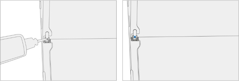
- Apply thread locker to screws – Brush each of the new screws with Loctite 7649 Activator. Let each screw sit for 2 minutes after the applicator is applied before assembling the device.

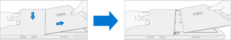
- Insert Foam Tabs – With the hinges still at approximately 45-degrees, start to slide the new kickstand’s foam tabs into the slots on the back of the device. Foam should slide in with minimal force – don't crumple the foam by using excess force. Don't slide the foam completely into the device – insert the foam tabs until 3/4th of the foam tabs are inside the device.
Caution
Don't use any tool or sharp object to help inserting the tabs into the slots. Doing so might result in damage to internal components.
- Slot outer lip of each hinge into the Kickstand – Using fingers on the underside of the kickstand and thumb on the topside, slightly rotate the kickstand on its axis as shown. The kickstand should rotate approximately 5-degrees to catch the outer lip of the hunger. Push the kickstand toward the device.
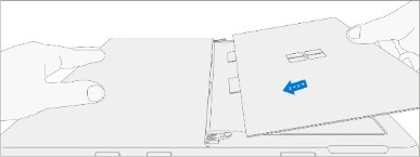
- Slip the Kickstand threaded bosses into the hinge recesses – While maintaining pressure on the kickstand to prevent it from backing out, rotate the kickstand down into place (image). The threaded bosses of the kickstand should slip into the recesses of the hinges.
- Rotate the Kickstand up – Firmly grip the kickstand near the hinges between your thumb and index fingers as shown. Rotate the kickstand from 45-degrees to approximately 90-degrees.

- Apply thread locker to screw bosses – Apply one drop of Loctite 243 thread locker to each screw boss.
- Install hinge screws – Use your finger to hold the back of the kickstand (shown) while installing the screws (3IP Torx-Plus Driver) until they're fully seated in each hinge. Ensure the kickstand is properly aligned and seated in the hinges, then tighten each screw an more ~quarter turn (~90 degrees). Be careful to only tighten the screws until snug to avoid stripping the kickstand threads. Ensure the screws don't fall into the hinge opening.

Perform a final inspection of the Kickstand – Fold down the Kickstand and peel off the protective plastic from the kickstand logo (if present). Verify that the side edges of the kickstand are aligned with the midframe walls, and that there are no obvious steps/gaps between the kickstand and the enclosure.
Clean the device – Wipe the device thoroughly (including under the kickstand) with a microfiber cloth to remove any fingerprints.
Solid State Drive Door Replacement Process
Preliminary Requirements
Important
Be sure to follow all special (bolded) notes of caution within each process section.
Required Tools
- N/A
Primary Components
- Solid State Drive Door (Refer to the Illustrated Service Parts List)
Additional Components (Ordered Separately)
- N/A
Procedure - Removal (Solid State Drive Door)
Position Device – Place the device screen-down on a clean surface.
Extend the kickstand to approximately 90-degrees.

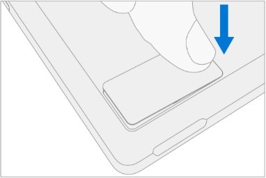
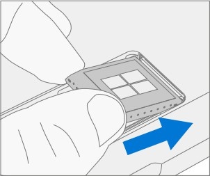
- Remove the SSD Door – Press down on the divot on top of the SSD door until it pops open. Lift it up and out of the device.
Procedure - Installation (Solid State Drive Door)
- Install the SSD Door – With the kickstand open to approximately 90 degrees, slot the replacement SSD Door into the SSD slot, and press down to install. Ensure the side with the divot is inserted as shown.
Removable Solid-State Drive (rSSD) Replacement Process
Preliminary Requirements
Important
Be sure to follow all special (bolded) notes of caution within each process section.
Required Tools
- 3IP (Torx-plus) driver
- Nylon Spudger
- Anti-static wrist strap (1 MOhm resistance)
- Microfiber / Lint free cloth
- Soft ESD-safe mat
- USB drive with Surface Diagnostic Toolkit
- USB drive with Surface Recovery Image
Primary Components
- Removable Solid-State Drive (Refer to the Illustrated Service Parts List)
- 1x Removable Solid-State Drive Screw; bag labeled with

- Part Number 13NL-5JN0V01/02, M1.2*L1.5 3IP
- 1x Removable Solid-State Drive Screw; bag labeled with
Additional Components (Ordered Separately)
- N/A
Procedure - Removal (Removable Solid-State Drive)
- Position Device – Place the device screen-down on a clean surface.
- Remove Solid State Drive Door – See Procedure – Removal (Solid State Drive Door) for instructions.
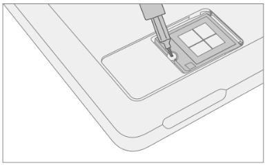
- Remove Removable Solid State Drive screw – Use a 3IP (Torx-plus) driver to remove the screw securing the Removal Solid State Drive (rSSD).

- Remove the Removable Solid-State Drive – The rSSD should lift upwards to approximately 15-degrees after the screw is removed. Carefully grab the sides of the rSSD case and pull it out of the Motherboard socket at the same approximately 15-degree angle. A Nylon Spudger can be used to lift up the rSSD.
Procedure - Installation (Removable Solid-State Drive)
Important
Only a Removable Solid-State Drive of the same capacity should be replaced in the device. This ensures proper physical and thermal performance.
- Insert Removable Solid-State Drive - Insert the connector end of the rSSD into the rSSD connector on the mainboard at a 15-degree angle.
- Install Removable Solid-State Drive screw - Use a 3IP
(Torx-plus) driver to install the rSSD screw, labeled with
 on the bag, until the screw is snug and seated. Turn the screw
another 45 degrees (1/8th turn) to fully fasten.
on the bag, until the screw is snug and seated. Turn the screw
another 45 degrees (1/8th turn) to fully fasten.
- Install Solid-State Drive Door – See Procedure – Installation (Solid-State Drive Door) for instructions.
Important
If you're swapping Removable Solid-State Drives between devices, you'll need the user’s BitLocker Recovery Key to unlock the drive and allow it to boot into the Windows Operating System. The user must also remember any sign-in passwords and/or pins to access the device post-repair.
- Imaging – All replacement Removable Solid-State Drives ship without a Windows Image. To restore the factory image for your Surface device, refer to the Surface Imaging Tools link in the Software Tools section of this document.
- Run the Surface Diagnostic Tool – After the device has completed the imaging step, power on the device and allow it to boot to the Windows desktop. Insert a USB drive with the Surface Diagnostic Tool loaded (see Software Tools for links). Run all the available Surface Diagnostic Tool diagnostic tests to ensure the device functions as expected post-repair.
Display Module Replacement Process
Preliminary Requirements
Important
Be sure to follow all special (bolded) notes of caution within each process section.
Required Tools
- 3IP (Torx-plus) driver
- Anti-static wrist strap (1 MOhm resistance)
- Microfiber / Lint free cloth
- Soft ESD-safe mat
- Isopropyl alcohol (91 % or greater IPA)
- Cleaning swab
- USB drive with Surface Diagnostic Toolkit
- Nylon Spudger
- Plastic Opening pick
- Two 2-in spring clamps
- Metric ruler
- Fine tipped marker
- 3mm Allen Driver
- Foam Pad (see the Tools section for specifics)
- Display bonding weights (see the Tools section for specifics)
- Surface Display Debonding Tool (M1214770-001) - iFixit
- Surface Display Bonding Frame (M1260233-001) - iFixit
Primary Components
- Display Module (Refer to Illustrated Service Parts List)
- Surface Pro 11th & 10th Edition for Business
- 1 x Removable Solid-State Drive Screw; bag labeled with
- Part Number 13NL-5JN0V01/02, M1.2*L1.5 3IP
- 1 x TDM Shield lid – 13NL-5LN0H01
- 1 x TDM PSA Top – 13NL-5LUA41/43
- 1 x TDM PSA Right – 13NL-5LU0441/43
- 1 x TDM PSA Left – 13NL-5LU0741/43
- 1 x TDM PSA Bottom – 13NL-5LU0961/63
- 1 x Left Speaker Mesh – 13NL-5LU0532/33
- 1 x Right Speaker Mesh – 13NL-5LU0842/43
- 1 x Shielding tape – 13NL-5JU1501/02
- 2 x NFC foam – 13NL-5MU1A01
- 1 x Removable Solid-State Drive Screw; bag labeled with
- Surface Pro for Business 11th Edition with Intel
- 1 x Removable Solid-State Drive Screw; bag labeled with
- Part Number 13NL-5JN0V01/02, M1.2*L1.5 3IP
- 1 x TDM Shield lid – 13NL-5QN1311
- 1 x TDM PSA Top – 13NL-5LUA41/43
- 1 x TDM PSA Right – 13NL-5LU0441/43
- 1 x TDM PSA Left – 13NL-5LU0741/43
- 1 x TDM PSA Bottom – 13NL-5LU0961/63
- 1 x Left Speaker Mesh – 13NL-5LU0532/33
- 1 x Right Speaker Mesh – 13NL-5LU0842/43
- 1 x TDM Shielding tape – 13NL-5QU0P13/14
- 2 x NFC foam – 13NL-5MU1A01
- 1 x Removable Solid-State Drive Screw; bag labeled with
Additional Components (Ordered Separately)
- N/A
Procedure - Preparation (Display)
Important
This section is only for instances where you're replacing the display. If the display is being re- used, then this section isn't required. If display is unusable due to damage or fault, connect an external monitor to the device to perform these steps.
Important
Ensure the light levels of your work remain consistent during the software calibration process.
Warning
DO NOT use a heat gun or hair dryer to debond the display.
- Connect USB – Connect USB with the Surface Diagnostic Toolkit (SDT) loaded to an available USB port on the device under repair.
- Power on device – Connect a power supply to the device. Press the power button on the device to power on the device. Allow it to boot to the Windows Desktop before continuing.
- Launch SDT – From the Windows Desktop, use Windows Explorer to navigate to the USB drive. Select the SDT executable (.exe) to launch the Surface Diagnostic Toolkit.
- Run Touch Display Setup – From the SDT launch screen, select Repair from the drop-down menu. Next, select Repair Setup and Validation to enter the selection screen. Run the Touch Display (Setup) tool to prepare your device for display replacement. Follow all on-screen instructions and allow the device to shut down when prompted. Disconnect the Power Supply and remove the USB drive before proceeding forward.
Procedure - Removal (Display Module)
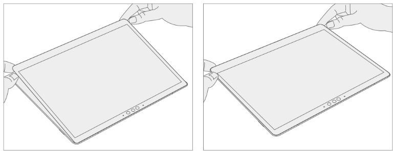
Position Device – Place the device screen-down on a clean surface.
Remove the Removable Solid-State Drive Door – Refer to the Procedure – Removal (Solid-State Drive) section for detailed instructions.
Remove the Removable Solid-State Drive – Remove 1 screw and remove the rSSD. See the Procedure – Removal (Removable Solid-State Drive) section for detailed instructions.
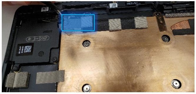
Remove the speaker meshes – Close the kickstand and place the device face up on a clean surface. Using the opening pick, or plastic opening tool, widen the gap as shown by pushing the flat edge into the gap and moving it side to side along the device edge at the opening. The speaker mesh might crumple or fold into the device – both results are okay as it will be removed entirely and replaced during installation. Repeat this process for the other speaker’s mesh.
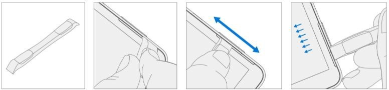
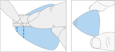
- Mark pick depth markers onto opening pick – Using a metric ruler, draw a mark on the plastic pick at 2mm and 8mm as shown in the image .
Prepare the Surface Display Debonding Tool –
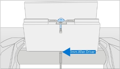
- Install the marked pick in the holder with the marks visible. Use a 3mm Allen Driver to adjust the pick height to the 2-mm mark.
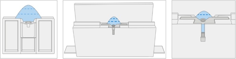
- Clamp the debonding tool to the edge of your workbench using a Hand Clamp on each side as shown in the image. Ensure the cut depth adjust can be accessed while the tool is clamped down. If it cannot be accessed, the clamps will have to be removed to access the bottom of the tool and then re-clamped after adjusting the height.
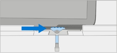
- Ensure the pick height is at 2mm before starting. Place the right-side speaker edge of the device in the Surface Debonding Tool just above the marked pick. Ensure the pick enters the gap between the display and the enclosure edge.
- While holding the device with both of your hands, push the device to the right through the Surface Debonding Tool track to cut through the right edge of the device. The device might be pushed side-to-side over the pick on this edge to ensure separation between the screen and the device.
- When you have reached the bottom right corner, rotate the device along the Surface Debonding Tool track. Continue to push the device to the right through the Surface Debonding Tool track to cut through the bottom edge. The device might be pushed side-to- side along this edge to ensure separation between the screen and the device.
- When you have reached the bottom left corner, rotate the device again in the Surface Debonding Tool track. Continue to push the device to the right through the Surface Debonding Tool track to cut through the left edge. Continue through the left speaker mesh area. The device might be pushed side-to-side along this edge to ensure separation between the screen and the device.

- When you have reached the top left corner, rotate the device in the Surface Debonding Tool track. Push the device to the right through the Surface Debonding Tool track to cut through the top edge. It is normal to feel more resistance on the top edge compared to the other edges due to the cameras. Continue to carefully add force and push the device over the pick.

- Once you have reached the top right corner, keep the top left edge of the device in the Surface Debonding Tool track. Using the 3mm Allen Driver, adjust the pick height to the 8mm mark. Ensure the pick edge stays engaged between the display and the enclosure edge. Push the device back and forth along this edge to ensure separation between the screen and the device. If the Surface Debonding Tool needs to be disassembled to access the pick height adjuster, carefully place the device aside while the pick height is changed to 8mm with the 3mm Allen Driver. Re-clamp the debonding tool and place the device into the debonding tool at the left speaker edge. Push the device towards the top left corner and rotate it to cut through the top edge.

Caution
Don't insert the pick more than 2mm along the left, right, or bottom edges of the display. The pick depth shouldn't exceed 8mm along the top edge of the display.
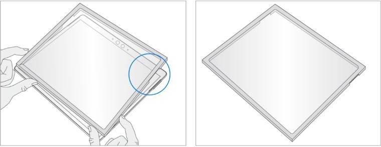
- Separate the Display Module from the enclosure – Gently pull up vertically on the top edge of the glass with one hand while pushing down on the enclosure to separate the glass. The screen will slowly peel off the device. Be careful when lifting the edges of the display as it is still connected to the device by an FPC connected to the Motherboard. Flip the display so that the glass screen rests on the bottom edge of the device.
Warning
It's recommended an ESD-safe Surface Battery Cover is placed across the device to protect the battery from any accidental damage during repair. Ensure the corners of the cover are always aligned with the corners of the device during repair. If the battery cover is misaligned during repair in any way, pause and realign the cover before continuing.
| Surface Pro 11th & 10th Edition for Business | Surface Pro for Business 11th Edition with Intel |
|---|

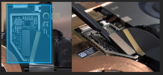
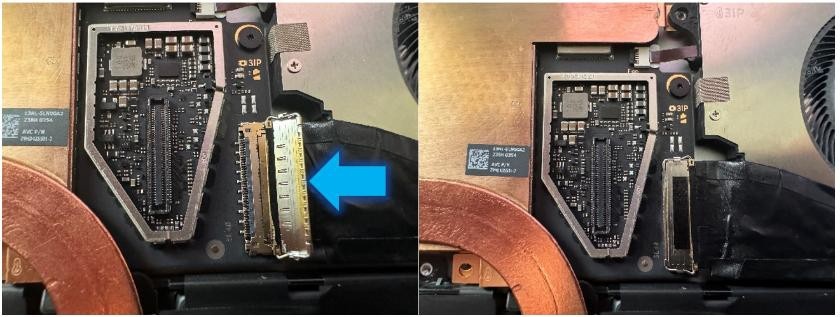
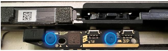
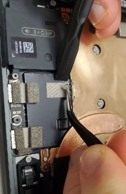
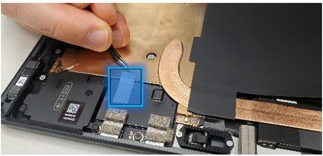
- Disconnect the display connector - Remove the metallic tape from the shield lid using a pair of ESD- safe tweezers. Next, remove the shield lid on the display connector using the ESD-safe tweezers. Lift at the corners shown and carefully free the shield lid. Disconnect the display connector by inserting the pointed edge of a Nylon Spudger under the left edge of the connector and peeling the connector off.
Important
Don't pull on the Display FPC to disconnect the display.
Surface Pro 11th & 10th Edition for Business
Surface Pro for Business 11th Edition with Intel Only
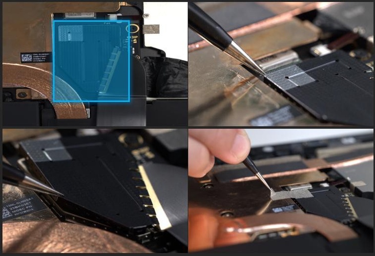
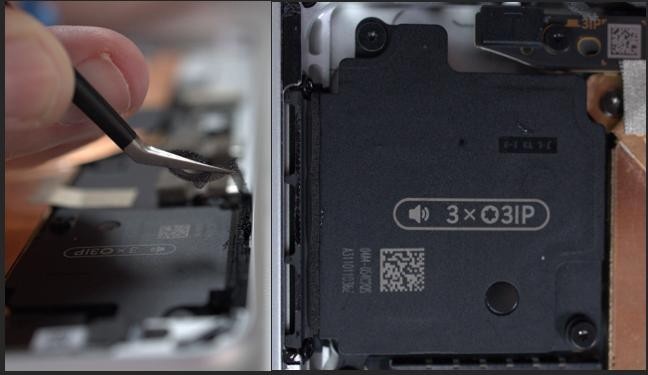
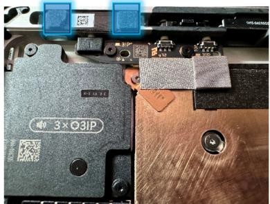
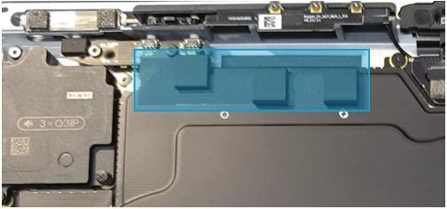
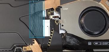
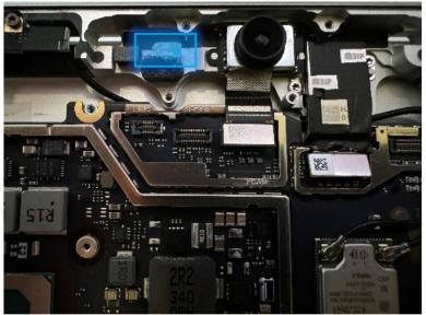
- Remove the speaker mesh and residual adhesive from the enclosure and display – Inspect the edges of the device and display and remove any adhesive with the Nylon spudger. Remove any remaining speaker mesh from the enclosure. Use the flat end of a nylon spudger to remove it by inserting the spudger between the speaker mesh and the enclosure. Confirm a successful removal of the speaker mesh and its adhesive by verifying the three cutouts of the enclosure are exposed, as shown.
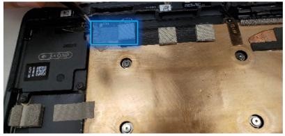
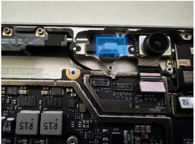
- Remove foams from the NFC – Locate the NFC in the top-left corner of the device. Using the Nylon spudger, carefully remove 2 foams from the NFC. These will be replaced.
- Clean enclosure - Using IPA and cleaning swabs, clean any residual adhesive from the enclosure edge. Ensure the area around the cameras (top edge) is clean and free of any dust or other contamination. Wipe the area around the camera with a lint-free cloth.
Procedure - Installation (Display Module)
Important
Verify the battery’s condition before beginning the installation of the display. Devices exhibiting battery issues as outlined in the Lithium-Ion Battery Inspection section of this guide require whole device replacement.
Important
Leave the protective cling on the new display during all installation steps to prevent damage to the display panel.
Important
Carefully inspect all internal areas of the enclosure for any foreign objects before installing the display.
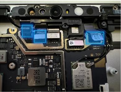
- Replace the NFC Foam (if present) – Locate the NFC in the top-left corner of the enclosure near the power button. Apply 2 new NFC foams as shown in the image. Align the edges of the foam with the white lines on the module.

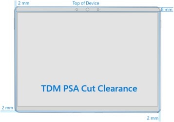
- Apply new Display Module adhesive – After cleaning the enclosure with IPA along the PSA bonding surfaces, wait at least 30 seconds before applying the new PSA strips to allow for the surface to dry completely. Carefully apply the 4 strips of PSA to the enclosure as shown in the image. Ensure the orientation of the PSA matches the enclosure outline before removing any liners. Align the PSA following the outline on the enclosure. Leave the blue liner on the PSA, as it will be removed at a later step.

- Install new Speaker Mesh – Perform the following:
- Place the display face-down on a clean ESD safe surface.
- Wipe down the outer edges of the display with a lint-free cloth.
- When reinstalling the original display, ensure the outer edges are clean of any PSA residue.
- Remove the protective liner from the Left Speaker Mesh.
- Using the clear handle, align the mesh into the display speaker opening on the right side of the device.
- Press on the mesh for 10 seconds to activate the adhesive.
- Carefully remove the clear handle.
- Repeat the process for the Right Speaker Mesh on the other side of the display.
Important
As the Display is facing down, the orientation of the Display is flipped vs what it will be when it's applied to the Device. The Left Speaker Mesh is applied to the Right side of the Display, in this orientation, and the Right Speaker Mesh is applied to the left side of the Display. Each Speaker Mesh is designed specifically to fit its specified side.

Connect the Display Module connector – Lay the display on the bottom edge as was done with the display was separated from the enclosure. Reconnect the Display FPC (Flexible Printed Circuit) into the mating connector on the motherboard. Press on the connector to ensure it's fully seated. Install a new shield over the Display FPC. Ensure all edges of the shield are snapped into place by pressing all around the shield edges with your finger. Add a new tape strip to the shield and thermal module by aligning it on the silver part on the shield.
Surface Pro 11th & 10th Edition for Business
Surface Pro for Business 11th Edition with Intel Only
Install the Display Module onto the Enclosure - While holding the display (with the screen facing up), remove the PSA liners from the Enclosure to expose the adhesive on all 4 edges. Align the display along the bottom edge first (Toe-in) and lower the rest of the display after alignment is found. Ensure that the glass sits flush in the Enclosure and doesn't rest anywhere on top of the Enclosure lip.
- Bond the adhesive – Place the Surface Display Bonding Frame on the device, ensuring that the cutouts on the sides line up with the buttons. Place a foam pad over the bonding frame. Place 32 kg of weight on top of the foam pad and bonding frame. Leave weight in place for 2 minutes to ensure PSA activation.
Important
Weight requirements can be found in the Preliminary Requirements (3) page. It's critical that the exact requirements are met (both weight, layout, and material) to ensure proper Display adhesion to the Enclosure.
- Ruck Weight Configuration –

- Steel Shot Bag Configuration –
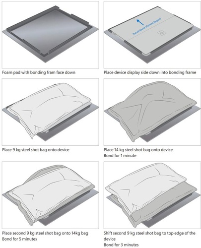
- After bonding inspection - Remove the weighted items from the device. Lift the device carefully out of the frame to avoid damage. Inspect the display for scratches, cracks, large gaps, and ensure it's flush to the enclosure.
- Install Removable Solid-State Drive – Turn the device over,
reinstall the solid-state drive and fasten a new screw from the bag
labeled
. Refer to the Procedure – Installation (Removable Solid-State section for detailed instructions.
- Install the Removable Solid-State Drive Door – Refer to the Procedure – Installation (Solid-State Drive) section for detailed instructions.
- Power on device to the Windows Desktop – Connect the device to power and press the power button. Allow the device to boot to the Windows Desktop before moving to the Procedure – Finalize (Display Module) section.
Procedure - Finalize (Display Module)
Important
This section is only for instances where you're replacing the display. If the display is being re- used, then this section isn't required. If display is unusable due to damage or fault, connect an external monitor to the device to perform these steps.
- Connect USB – Connect USB with the Surface Diagnostic Toolkit (SDT) loaded to an available USB port on the device under repair.
- Launch SDT – From the Windows Desktop, use Windows Explorer to navigate to the USB drive. Select the SDT executable (.exe) to launch the Surface Diagnostic Toolkit.
- Run Touch Display Calibration – From the SDT launch screen, select Repair from the drop-down menu. Next, select Repair Setup and Validation to enter the selection screen. Run the Touch Display (Calibration) tool to calibrate your new display. Follow all on-screen instructions and allow the device to restart when prompted.
Important
If the calibration fails, reboot the device, and attempt again. If the failure continues, then the display might be faulty and require replacement.
- Launch SDT – Once the device has rebooted and is at the Windows Desktop, use Windows Explorer to navigate to the USB drive. Select the SDT executable (.exe) to launch the Surface Diagnostic Toolkit.
- Run the Surface Diagnostic Toolkit (SDT) – Run all diagnostics to ensure the device is functioning as expected before moving forward.
- Final inspection - Remove the protective cling from the display. Verify the side edges of the display are still flush, and that there are no obvious steps/gaps between the Display and the Enclosure. Wipe the device thoroughly (including under the kickstand) with a microfiber cloth to remove any fingerprints.
Surface Connect Replacement Process
Preliminary Requirements
Important
Be sure to follow all special (bolded) notes of caution within each process section.
Required Tools
- 3IP (Torx-plus) driver
- Anti-static wrist strap (1 MOhm resistance)
- Microfiber / Lint free cloth
- Soft ESD-safe mat
- Isopropyl alcohol (91 % or greater IPA)
- Cleaning swab
- USB drive with Surface Diagnostic Toolkit
- Nylon Spudger
- Plastic Opening pick
- Two 2-in spring clamps
- Metric ruler
- Fine tipped marker
- 3mm Allen Driver
- Foam Pad (see the Tools section for specifics)
- Display bonding weights (see the Tools section for specifics)
- Surface Display Debonding Tool (M1214770-001) - iFixit
- Surface Display Bonding Frame (M1260233-001) - iFixit
- ESD-safe Surface Battery Cover - iFixit
Primary Components
- Surface Connect (Refer to Illustrated Service Parts List)
- Surface Pro 11th & 10th Edition for Business
- 1 x Surface Connect Port Cable
- 2 x (M1.4 X 0.3 x 1.7) (Surface Connect Screws),

- Part Number – 13NL-5JN1M01/02
- 1 x M 1.2 * L1.5 3IP (SSD Screw),
- Part Number – 13NL-5JN0V01/02
- 1 x TDM Shield lid – 13NL-5LN0H01
- 1 x TDM PSA Top – 13NL-5LUA41/43
- 1 x TDM PSA Right – 13NL-5LU0441/43
- 1 x TDM PSA Left – 13NL-5LU0741/43
- 1 x TDM PSA Bottom – 13NL-5LU0961/63
- 1 x Left Speaker Mesh – 13NL-5LU0532/33
- 1 x Right Speaker Mesh – 13NL-5LU0842/43
- 1 x Shielding tape – 13NL-5JU1501/02
- 2 x NFC foam – 13NL-5MU1A01
- Surface Pro for Business 11th Edition with Intel
- 1 x Surface Connect Port Cable
- Part Number OLED - 1414-0EV60QS
- Part Number LCD - 1414-0EV70QS
- 2 x (M1.4 X 0.3 x 1.7) (Surface Connect Screws),
- Part Number – 13NL-5JN1M01/02
- 1 x M 1.2 * L1.5 3IP (SSD Screw),
- Part Number – 13NL-5JN0V01/02
- 1 x TDM Shield lid – 113NL-5QN1311
- 1 x TDM PSA Top – 13NL-5LUA41/43
- 1 x TDM PSA Right – 13NL-5LU0441/43
- 1 x TDM PSA Left – 13NL-5LU0741/43
- 1 x TDM PSA Bottom – 13NL-5LU0961/63
- 1 x Left Speaker Mesh – 13NL-5LU0532/33
- 1 x Right Speaker Mesh – 13NL-5LU0842/43
- 1 x TDM Shielding tape – 13NL-5QU0P13/14
- 2 x NFC foam – 13NL-5MU1A01
- 1 x Surface Connect Port Cable
Additional Components (Ordered Separately)
- N/A
Procedure - Removal (Surface Connect)
- Remove the Removable Solid-State Drive Door – Refer to the Procedure – Removal (Solid-State Drive section for detailed instructions.
- Remove the Removable Solid-State Drive – Remove 1 screw and the rSSD. Refer to the Procedure – Removal (Removable Solid-State Drive section for detailed instructions.
- Remove the Display Module – Using the Surface Debonding Tool, debond the display. Remove 1 shielding tape, 2 NFC foams and 1 shield lid and disconnect the FPC. Refer to the Procedure – Removal (Display Module) section for detailed instructions.
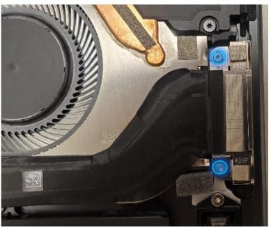
- Disconnect the Surface Connect Port connector from the Motherboard - Use the plastic opening tool to release the locking bar and disconnect the Surface Connect Port connector from the Motherboard.
- Remove the Surface Connect Port screws – Use a 3IP (Torx-plus)
driver to remove both Surface Connect Port screws labeled with
.
Important
The Surface Connect Port is magnetized. Be careful not to let the screws stick to it during removal.
- Remove the Surface Connect Port cable – Gently peel the Surface Connect Port up from the chassis from left to right. Clean any residual adhesive left behind on the thermal module with IPA and a cleaning swab. When reusing the Surface Connect, peel off the residual adhesive from the Surface Connect.

Procedure - Installation (Surface Connect Port)
- Apply Surface Connect Adhesive (Re-use only) - If reusing the Surface Connect Port, apply the sheet of adhesive (Part Number 13NL-5JU2Z01) to the back of the cable. Align the curved edge as shown to the cable. Don't remove the bottom liner yet.
- Connect Surface Connect Port cable to the Motherboard - Connect the Surface Connect Port cable to the motherboard by inserting the connector from the right. Press down on the locking buckle to secure the connection.
- Install Surface Connect Port screws – Insert the port into the
enclosure on the right with a toe-in. Use a 3IP (Torx-plus) driver
to install 2 screws labeled
until they're snug
and seated. Turn each screw another 45 degrees (1/8 turn) until
fully fastened.
Important
The Surface Connect Port is magnetized. Be careful not to let the screws stick to it during removal.
- Remove Surface Connect Port cable liner and install - Remove the Surface Connect Port cable liner to expose the adhesive. Press down on the cable from left to right to glue the cable in place. Keep pressing along the cable to get rid of any bumps.
- Install the Display Module – Install 2 new NFC foams. Reconnect the display FPC and install a new shield and shield tape on top. Align new PSA strips and install new speaker meshes on the display. Align the display on the bottom edge and press onto device. Use bonding frame tool to apply weight. Refer to the Procedure – Installation (Display Module) section for detailed instructions.
- Install the Removable Solid-State Drive – Turn the device over,
reinstall the solid-state drive and fasten a new screw from the bag
labeled
. Refer to the Procedure – Installation (Removable Solid-State Drive)section for detailed instructions.
- Install the Removable Solid-State Drive Door – Refer to the Procedure – Installation (Solid-State Drive Door) section for detailed instructions.
- Power on device – Carefully place device screen side up. Connect the device to a power supply, open display, and power on to the Windows desktop screen.
- Run the Surface Diagnostic Toolkit (SDT) - Run SDT’s full diagnostic test to ensure device functions as expected.
- Power down device – Power down device using the OS start menu.
Speakers Replacement Process
Preliminary Requirements
Important
Be sure to follow all special (bolded) notes of caution within each process section.
Required Tools
- 3IP (Torx-plus) driver
- Anti-static wrist strap (1 MOhm resistance)
- Microfiber / Lint free cloth
- Soft ESD-safe mat
- Isopropyl alcohol (91 % or greater IPA)
- Cleaning swab
- USB drive with Surface Diagnostic Toolkit
- Nylon Spudger
- Plastic Opening pick
- Two 2-in spring clamps
- Metric ruler
- Fine tipped marker
- 3mm Allen Driver
- Foam Pad (see the Tools section for specifics)
- Display bonding weights (see the Tools section for specifics)
- Surface Display Debonding Tool (M1214770-001) - iFixit
- Surface Display Bonding Frame (M1260233-001) - iFixit
- ESD-safe Surface Battery Cover - iFixit
Primary Components
- Speakers (Refer to Illustrated Service Parts List)
- Surface Pro 11th & 10th Edition for Business
- 1 x Left Speaker
- Part Number - 04A4-054C2QS
- 1 x Right Speaker
- Part Number - 04A4-054B2QS
- 6 x M1.4*L1.9 3IP (L&R Speaker Screws),

- Part Number – 13NL-5LN0B01/03
- 1 x M 1.2 * L1.5 3IP (SSD Screw),
- Part Number – 13NL-5JN0V01/02
- 1 x TDM Shield lid – 13NL-5LN0H01
- 1 x TDM PSA Top – 13NL-5LUA41/43
- 1 x TDM PSA Right – 13NL-5LU0441/43
- 1 x TDM PSA Left – 13NL-5LU0741/43
- 1 x TDM PSA Bottom – 13NL-5LU0961/63
- 1 x Left Speaker Mesh – 13NL-5LU0532/33
- 1 x Right Speaker Mesh – 13NL-5LU0842/43
- 1 x Shielding tape – 13NL-5JU1501/02
- 2 x NFC foam – 13NL-5MU1A01
- 1 x Left Speaker
- Surface Pro for Business 11th Edition with Intel
- 1 x Left Speaker
- Part Number - 04A4-054C2QS
- 1 x Right Speaker
- Part Number - 04A4-054B2QS
- 6 x M1.4*L1.9 3IP (L&R Speaker Screws),
- Part Number – 13NL-5LN0B01/03
- 1 x M 1.2 * L1.5 3IP (SSD Screw),
- Part Number – 13NL-5JN0V01/02
- 1 x TDM Shield lid – 13NL-5QN1311
- 1 x TDM PSA Top – 13NL-5LUA41/43
- 1 x TDM PSA Right – 13NL-5LU0441/43
- 1 x TDM PSA Left – 13NL-5LU0741/43
- 1 x TDM PSA Bottom – 13NL-5LU0961/63
- 1 x Left Speaker Mesh – 13NL-5LU0532/33
- 1 x Right Speaker Mesh – 13NL-5LU0842/43
- 1 x TDM Shielding tape – 13NL-5QU0P13/14
- 2 x NFC foam – 13NL-5MU1A01
- 1 x Left Speaker
Additional Components (Ordered Separately)
- N/A
Procedure - Removal (Speakers)
- Remove the Removable Solid-State Drive Door – Refer to the Procedure – Removal (Solid-State Drive section for detailed instructions.
- Remove the Removable Solid-State Drive - Remove 1 screw and remove the rSSD. Refer to the Procedure – Removal (Removable Solid-State Drive) instructions.
- Remove the Display Module – Using the Surface Debonding Tool, debond the display. Remove 1 shielding tape, 2 NFC foams and 1 shield lid and disconnect the FPC. Refer to the Procedure – Removal (Display Module) section for detailed instructions.
- Remove screws from left speaker – Using a 3IP (Torx-plus) drive, remove the three marked screws from the left speaker and lift out of the enclosure.
- Remove screws from right speaker – Using a 3IP (Torx-plus) drive, remove the three marked screws from the right speaker and lift out of the enclosure. DO NOT remove the Graphite sheet – bend it as needed to access the speaker.
Procedure - Installation (Speakers)
- Insert the Left Speaker – Place the left speaker into the
enclosure making sure to align the screw holes on the speaker with
the holes in the enclosure. Using a 3IP (Torx-plus) driver, install
3 screws from the bag labeled with
, turning each screw until finger tight then tighten each by an
more 1/8th turn (45-degrees).
- Install the Right Speaker – Place the right speaker into the
enclosure making sure to align the screw holes on the speaker with
the holes in the enclosure. Using a 3IP (Torx-plus) driver, install
3 screws from the bag labeled with
, turning each screw until finger tight then tighten each by an
more 1/8th turn (45-degrees). DO NOT remove the Graphite
sheet – bend it as needed to access the speaker.
- Install the Display Module - Install 2 new NFC foams. Reconnect the display FPC and install a new shield and shield tape on top. Align new PSA strips and install new speaker meshes on the display. Align the display on the bottom edge and press onto device. Use bonding frame tool to apply weight. Refer to the Procedure – Installation (Display Module) section for detailed instructions.
- Install the Removable Solid-State Drive – Turn the device over,
reinstall the solid-state drive and fasten a new screw from the bag
labeled
. Refer to the Procedure – Installation (Removable Solid-State Drive)
section for detailed instructions.
- Install the Removable Solid-State Drive Door – Refer to the Procedure – Installation (Solid-State Drive Door) section for detailed instructions.
- Power on device – Carefully place device screen side up. Connect the device to a power supply, open display, and power on to the Windows desktop screen.
- Run the Surface Diagnostic Toolkit (SDT) - Run SDT’s full diagnostic test to ensure device functions as expected.
- Power down device – Power down device using the OS start menu.
Buttons Replacement Process
Preliminary Requirements
Important
Be sure to follow all special (bolded) notes of caution within each process section.
Required Tools
- 3IP (Torx-plus) driver
- Anti-static wrist strap (1 MOhm resistance)
- Microfiber / Lint free cloth
- Soft ESD-safe mat
- Isopropyl alcohol (91 % or greater IPA)
- Cleaning swab
- USB drive with Surface Diagnostic Toolkit
- Nylon Spudger
- Plastic Opening pick
- Two 2-in spring clamps
- Metric ruler
- Fine tipped marker
- 3mm Allen Driver
- Foam Pad (see the Tools section for specifics)
- Display bonding weights (see the Tools section for specifics)
- Surface Display Debonding Tool (M1214770-001) - iFixit
- Surface Display Bonding Frame (M1260233-001) - iFixit
- ESD-safe Surface Battery Cover - iFixit
Primary Components
- Buttons (Refer to Illustrated Service Parts List)
- Surface Pro 11th & 10th Edition for Business
- 1 x Buttons PCBA
- Part Number - 69NL5LD10A01
- 1 x Power button
- Platinum Part Number - 13NL-5LQ0701
- Graphite Part Number - 13NL-5LQ0A01
- 1 x Volume button
- Platinum Part Number - 13NL-5LQ0B01
- Graphite Part Number - 13NL-5LQ0E01
- 1 x Power and Volume Retaining Clip
- Part Number - 13NL-5LQ0F01
- 2 x M1.4*L1,9 3IP (Button PCBA Screws),

- Part Number - 13NL-5LN0B01/03
- 1 x M 1.2 * L1.5 3IP SSD Screw,
- Part Number – 13NL-5JN0V01/02
- 1 x VC gasket - 13NL-5LU0D11
- 1 x VC gasket (OLED) – 13NL-5MU0L21
- 1 x NFC PSA - 13NL-5MU1B01
- 1 x TDM Shield lid – 13NL-5LN0H01
- 1 x TDM PSA Top – 13NL-5LUA41/43
- 1 x TDM PSA Right – 13NL-5LU0441/43
- 1 x TDM PSA Left – 13NL-5LU0741/43
- 1 x TDM PSA Bottom – 13NL-5LU0961/63
- 1 x Left Speaker Mesh – 13NL-5LU0532/33
- 1 x Right Speaker Mesh – 13NL-5LU0842/43
- 1 x Shielding tape – 13NL-5JU1501/02
- 2 x NFC foam – 13NL-5MU1A01
- 1 x Buttons PCBA
- Surface Pro for Business 11th Edition with Intel
- 1 x Buttons PCBA
- Part Number - 69NL5LD10A01
- 1 x Power button
- Platinum Part Number - 13NL-5LQ0701
- Graphite Part Number - 13NL-5LQ0A01
- 1 x Volume button
- Platinum Part Number - 13NL-5LQ0B01
- Graphite Part Number - 13NL-5LQ0E01
- 1 x Power and Volume Retaining Clip
- Part Number - 13NL-5LQ0F01
- 2 x M1.4*L1,9 3IP (Button PCBA Screws),
- Part Number - 13NL-5LN0B01/03
- 1 x M 1.2 * L1.5 3IP SSD Screw,
- Part Number – 13NL-5JN0V01/02
- 1 x T1 gasket LCD - 13NL-5QU0X03/04
- 1 x T1 gasket OLED - 13NL-5QU0Y03/04
- 1 x NFC PSA - 13NL-5MU1B01
- 1 x TDM Shield lid – 13NL-5QN1311
- 1 x TDM PSA Top – 13NL-5LUA41/43
- 1 x TDM PSA Right – 13NL-5LU0441/43
- 1 x TDM PSA Left – 13NL-5LU0741/43
- 1 x TDM PSA Bottom – 13NL-5LU0961/63
- 1 x Left Speaker Mesh – 13NL-5LU0532/33
- 1 x Right Speaker Mesh – 13NL-5LU0842/43
- 1 x TDM Shielding tape – 13NL-5QU0P13/14
- 2 x NFC foam – 13NL-5MU1A01
- 1 x Buttons PCBA
Additional Components (Ordered Separately)
- N/A
Procedure - Removal (Buttons)
Remove the Removable Solid-State Drive Door – Refer to the Procedure – Removal (Solid-State Drive section for detailed instructions.
Remove the Removable Solid-State Drive - Remove 1 screw and remove the rSSD. Refer to the Procedure – Removal (Removable Solid-State Drive) section for detailed instructions.
Remove the Display Module – Using the Surface Debonding Tool, debond the display. Remove 1 shielding tape, 2 NFC foams and 1 shield lid and disconnect the FPC. Refer to the Procedure – Removal (Display Module) section for detailed instructions.
Remove the tape and foam – Locate and remove the tape and foam that stretches between the button PCB and Thermal Module. Clean any residual tape from the thermal module with IPA and cleaning swabs.
Surface Pro 11th & 10th Edition for Business
Surface Pro for Business 11th Edition with Intel Only
Remove Buttons PCBA Screws – Using a 3IP (Torx-Plus) driver, remove the 2 screws as shown in the image (yellow circles) that are labeled with
. Once removed, lift the button board out of the device. If the
button board is being reused, clean any residual tape from the board
with IPA and cleaning swabs.
- Peel back the NFC module – Using a Nylon Spudger, carefully peel back the NFC module to expose the buttons. DO NOT remove the NFC module. Carefully clean the PSA off the bottom of the NFC with IPA and cleaning swabs.
- Remove the Button clips – Using a Nylon Spudger or a pair of ESD-Safe Tweezers, get under the edge of the button clip and leverage them up until the clip pops out. Remove both clips.
- Remove the Buttons - Using a Nylon Spudger or a pair of tweezers, push on the button posts to remove the buttons from the enclosure.
Procedure - Installation (Buttons)
- Insert the new buttons – Using your fingers, insert the button posts into enclosure from the outside. Ensure the button posts align with the holes in the enclosure.
- Install the button retention clip – Align the clip-on top of the button posts and press down until it clicks in place. Ensure the “Button Side” faces the top edge of the device as shown. You'll hear an audible click once the buttons are captured in the enclosure.

- Remove the plastic tab – Bend the plastic tab front to back repeatedly until it breaks off
from the clips.

- Reinstall the NFC Module and Foams (if present) – Install the PSA liner (13NL-5MU1B01) to the backside of the NFC module and press the NFC module back into the Enclosure. The PSA should sit behind the tab at the end and line up with the width of the module as shown .

- Install the button PCB – Insert the button PCB into the device,
aligning the 2 screw holes with the screw bosses. Using a 3IP
(Torx-plus) driver, install the two screws marked with
, turning each screw until finger tight, the tighten each by an
more 1/8th turn (45-degrees).
Install tapes and foams – Remove the liner from the new VC gasket for SP11 & SP10 (13NL-5LU0D11) or T1 gasket for SP11 with Intel (13NL-5QU0X03/04) and install it on the button PCB and thermal module. The top edge of the tape should align and cover the gold line on the PCB as shown.
Surface Pro 11th & 10th Edition for Business
Surface Pro for Business 11th Edition with Intel Only

Install the Display Module - Install 2 new NFC foams. Reconnect the display FPC and install a new shield and shield tape on top. Align new PSA strips and install new speaker meshes on the display. Align the display on the bottom edge and press onto device. Use bonding frame tool to apply weight. Refer to the Procedure – Installation (Display Module) section for detailed instructions.
Install the Removable Solid-State Drive – Turn the device over, reinstall the solid-state drive and fasten a new screw from the bag labeled
. Refer to the Procedure – Installation (Removable Solid-State Drive)
section for detailed instructions.Install the Removable Solid-State Drive Door – Refer to the Procedure – Installation (Solid-State Drive Door) section for detailed instructions.
Power on device – Carefully place device screen side up. Connect the device to a power supply, open display, and power on to the Windows desktop screen.
Run the Surface Diagnostic Toolkit (SDT) - Run SDT’s full diagnostic test to ensure device functions as expected.
Power down device – Power down device using the OS start menu.
Thermal Module + Fan Replacement Process
Preliminary Requirements
Important
Be sure to follow all special (bolded) notes of caution within each process section.
Required Tools
- 3IP (Torx-plus) driver
- Anti-static wrist strap (1 MOhm resistance)
- Microfiber / Lint free cloth
- Soft ESD-safe mat
- Isopropyl alcohol (91 % or greater IPA)
- Cleaning swab
- USB drive with Surface Diagnostic Toolkit
- Nylon Spudger
- Plastic Opening pick
- Two 2-in spring clamps
- Metric ruler
- Fine tipped marker
- 3mm Allen Driver
- Foam Pad (see the Tools section for specifics)
- Display bonding weights (see the Tools section for specifics)
- Surface Display Debonding Tool (M1214770-001) - iFixit
- Surface Display Bonding Frame (M1260233-001) - iFixit
- ESD-safe Surface Battery Cover - iFixit
Primary Components
- Thermal Module (Refer to Illustrated Service Parts List)
- Surface Pro 11th & 10th Edition for Business
- 8 x M1.4*L1.9 3IP (Thermal Module screws),

- Part Number – 13NL-5JN0Z01/02
- 1 x M1.4*L2 3IP (Fan Screw),

- Part Number – 13NL-5JN1111/12
- 1 x M1.6*L2.9 3IP (Battery side screw),

- Part Number – 13NL-5LN1001/03
- 4 x M1.2*1.8L 3IP (CPU Bracket screws),

- Part Number – 13NL-5EU1K01/02
- 2 x M1.4*L1,9 3IP (Button PCBA Screws),
- Part Number - 13NL-5LN0B01/03
- 2 x (M1.4 X 0.3 x 1.7) (Surface Connect Screws),
- Part Number – 13NL-5JN1M01/02
- 1 x M 1.2 * L1.5 3IP (SSD Screw),
- Part Number – 13NL-5JN0V01/02
- 1 x VC tape – 13NL-5LU0E11
- 1 x VC tape (OLED) – 13NL-5MU0K21
- 1 x Surface Connect PSA – 13NL-5JU2Z01
- 1 x VC gasket – 13NL-5LU0D11
- 1 x VC gasket (OLED) – 13NL-5MU0L21
- 1 x VC tape – 13NL-5LU0E11
- 1 x TDM Shield lid – 13NL-5LN0H01
- 1 x TDM PSA Top – 13NL-5LUA41/43
- 1 x TDM PSA Right – 13NL-5LU0441/43
- 1 x TDM PSA Left – 13NL-5LU0741/43
- 1 x TDM PSA Bottom – 13NL-5LU0961/63
- 1 x Left Speaker Mesh – 13NL-5LU0532/33
- 1 x Right Speaker Mesh – 13NL-5LU0842/43
- 2 x Shielding tape – 13NL-5JU1501/02
- 2 x NFC foam – 13NL-5MU1A01
- 8 x M1.4*L1.9 3IP (Thermal Module screws),
- Surface Pro for Business 11th Edition with Intel
- 1 x Thermal Module / Fan with TIM LCD – 13NL-5QN0532 / 13NL-5QB0D11
- 1 x Thermal Module / Fan with TIM OLED – 13NL-5QN0632 / 13NL-5QB0E11
- 6 x M1.4*L1.9 3IP (Thermal Module screws),
- Part Number – 13NL-5JN0Z01/02
- 1 x M1.4*L2 3IP (Fan Screw),
- Part Number – 13NL-5JN1111/12
- 1 x M1.6*L2.9 3IP (Battery side screw),
- Part Number – 13NL-5LN1001/03
- 4 x M1.2*1.8L 3IP (CPU Bracket screws),
- Part Number – 13NL-5EU1K01/02
- 2 x M1.4*L1,9 3IP (Button PCBA Screws),
- Part Number - 13NL-5LN0B01/03
- 2 x (M1.4 X 0.3 x 1.7) (Surface Connect Screws),
- Part Number – 13NL-5JN1M01/02
- 1 x M 1.2 * L1.5 3IP (SSD Screw),
- Part Number – 13NL-5JN0V01/02
- 1 x Surface Connect PSA – 13NL-5JU2Z01
- 1 x T1 gasket LCD - 13NL-5QU0X03/04
- 1 x T1 gasket OLED - 13NL-5QU0Y03/04
- 1 x T1 Shield Lid – 13NL-5QN0X01
- 1 x TDM Shield lid – 13NL-5QN1311
- 1 x TDM PSA Top – 13NL-5LUA41/43
- 1 x TDM PSA Right – 13NL-5LU0441/43
- 1 x TDM PSA Left – 13NL-5LU0741/43
- 1 x TDM PSA Bottom – 13NL-5LU0961/63
- 1 x Left Speaker Mesh – 13NL-5LU0532/33
- 1 x Right Speaker Mesh – 13NL-5LU0842/43
- 1 x TDM Shielding tape – 13NL-5QU0P13/14
- 2 x NFC foam – 13NL-5MU1A01
Additional Components (Ordered Separately)
- N/A
Procedure - Removal (Thermal Module + Fan)
- Remove the Removable Solid-State Drive Door – Refer to the Procedure – Removal (Solid-State Drive section for detailed instructions.
- Remove the Removable Solid-State Drive - Remove 1 screw and remove the rSSD. Refer to the Procedure – Removal (Removable Solid-State Drive) section for detailed instructions.
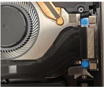
- Remove the Display Module – Using the Surface Debonding Tool, debond the display. Remove 1 shielding tape, 2 NFC foams and 1 shield lid and disconnect the FPC. Refer to the Procedure – Removal (Display Module) section for detailed instructions.
- Remove the Surface Connect Port Cable – Remove 2 screws (
) and peel the Surface
Connect off the thermal module. Refer to the Procedure – Removal (Surface Connect Port) section for detailed instructions.
- Remove the button PCB and gasket – Remove 2 screws (
) and the tape and foam spreading across the button board and
thermal module. Remove the button board from the device but leave
the buttons in place. Refer to the Procedure – Removal (Buttons) section for detailed
instructions.
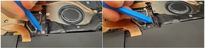
- Disconnect the fan from the Motherboard – Using tweezers, lift the tab and pull the FPC out from the connector on the motherboard.

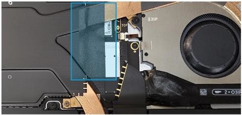
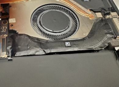
- Remove Shielding Tape – Using a set of ESD-Safe Tweezers, remove the shielding tape beneath the left speaker as shown. Be careful not to remove the shield from underneath using a Nylon spudger to hold it down.
Remove tapes and foams from the top edge - Using a set of ESD-Safe Tweezers, remove the VC or T1 tape.
Surface Pro 11th & 10th Edition for Business Surface Pro for Business 11th Edition with Intel

Remove the SOC Shield – Using an ESD-safe tweezer, begin lifting in the right corner and only along the top edge to carefully remove the SOC shield covering the Thermal Module and SOC.
Surface Pro for Business 11th Edition with Intel Only
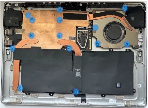
Remove Thermal Module screws – Use a 3IP (Torx-Plus) driver to remove the 14 (SP11 & SP10) or 12 (SP11 with Intel) screws securing the thermal module to the motherboard, designated with
 and
and  in the device next to the screws. Use caution to not lose any screws in the enclosure during removal as they aren't captive.
Surface Pro 11th & 10th Edition for Business
Surface Pro for Business 11th Edition with Intel
Release the Thermal Module from the Motherboard – Using the plastic opening tool, apply light pressure under each edge to slowly free the main plate from the thermal material underneath.

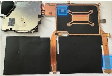
Lift and remove Thermal Module from Enclosure – While gripping the Thermal Module at the specific points shown, slowly lift and twist clockwise to free it from the enclosure. Don't damage or wrinkle the Graphite sheets.
Surface Pro 11th & 10th Edition for Business Surface Pro for Business 11th Edition with Intel

Clean any Thermal Interface Material from the Motherboard – Using a Nylon Spudger, scrap any remaining Thermal Interface Material from the Motherboard. Use IPA and Cleaning Swabs to clean any residual Thermal Interface Material.
Surface Pro 11th & 10th Edition for Business

Surface Pro for Business 11th Edition with Intel

Clean any Thermal Interface Material from the thermal module (Re-use only) – If the thermal module is being reused, using a Nylon Spudger, scrap any remaining Thermal Interface Material from the locations circled. Use IPA and Cleaning Swabs to clean any residual Thermal Interface Material.
Surface Pro 11th & 10th Edition for Business

Surface Pro for Business 11th Edition with Intel

Procedure - Installation (Thermal Module + Fan)
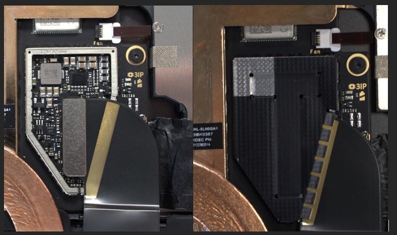
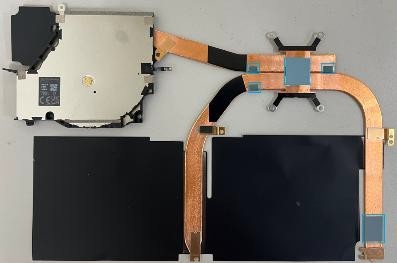
Apply new Thermal Pads (Re-use only) – This step is only required if you're reusing the original Thermal Module. If you're installing a new Thermal Module, skip this step and begin with Step 2.
For Surface Pro 11 & 10: Apply the VC pad (13NL-5MU1001) and the HP pad (13NL-5MU0Y01) to the back of the thermal module as shown in the image.
For Surface Pro 11 with Intel: Apply the THM pad (13NL-5QU0W01), the PMIC Pads (13NL- 5QU1301) and the HP pad (13NL-5QU1201) to the back of the thermal module as shown in the image.
Follow the indentations and grooves to ensure pads are installed in the correct places.
Surface Pro 11th & 10th Edition for Business
Surface Pro for Business 11th Edition with Intel**
- Apply the CPU pad (SP11 & SP10: 13NL-5LU0Q01) or (SP11 with Intel: 13NL-5QU1101) to the center of the main chip on the motherboard as shown. Apply the THM Charger pad (SP11 with Intel: 13NL-5QU0W01) to the center of the charging chip as shown. Remove the plastic liner from all pads when ready to install the thermal module.
Surface Pro 11th & 10th Edition for Business

Surface Pro for Business 11th Edition with Intel

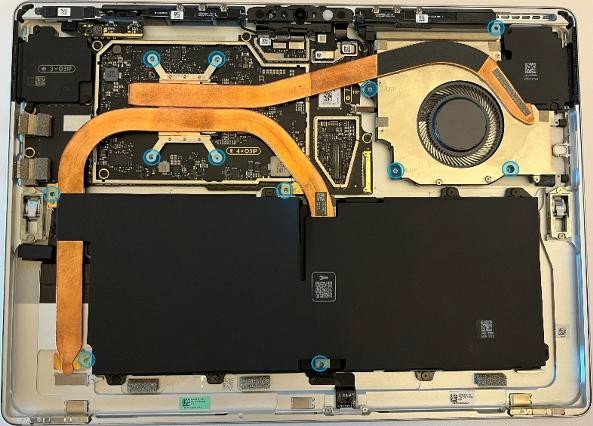
Install the Thermal Module – Align the thermal module and fan to the screw holes on the motherboard. Gently lower the Thermal Module into place. Fasten the screws in the order of the dash numbers, starting with the
screws and working your way to end with the
screws. The order for each screw is shown.
Note
The
screws around the main chip on the motherboard are installed in an
“x” pattern.
Surface Pro 11th & 10th Edition for Business

Surface Pro for Business 11th Edition with Intel

Important
The Thermal Module is fragile. Take extra care not to bend or twist the Thermal Module + Fan assembly. If any part of the Thermal Module or its heat pipes are bent, then the whole module must be replaced.
- Install the SOC Shield – Using your fingers, assisted with the flat end of a Nylon Spudger, gently apply the shield to cover the SOC. Using a finger, press on all the edges to ensure a solid connection is made.
Important
Pressing all of the edges of the SOC shield will ensure the shield is installed securely. Failure to do so might result in degradation in device performance. Avoid pressing on battery.
Surface Pro for Business 11th Edition with Intel Only

Install the Tape and Foams near button board – Install the tape with two foams (VC tape – 13NL- 5LU0E11), following the markings on the Thermal Module as shown. Begin by lining up the tape on the thermal module side with the Graphite lines, and then wrap the tape around the edge and stick the rest on the bucket. The bucket has etching to show where the tape will end up.
Surface Pro 11th & 10th Edition for Business

Connect the Fan to the Motherboard – Ensure the fan connector locking tab is up. Slide the Fan cable into the connector on the Motherboard. Press down on the locking tab to secure it. The FPC should slide in until the white lines are covered.

- Install Shielding Tape – Using a set of ESD-Safe Tweezers, install the shielding tape beneath the left speaker as shown. Use the silver cutout on the shield as your starting point for the tape.
Install the button PCB and gasket – Install the button PCB and secure with 2 screws (
). Assemble the tape and foam (VC gasket or T1 Tape) spreading
across the button board and thermal module. Refer to the
Procedure – Installation (Buttons) section for detailed
instructions.Surface Pro for Business 11th Edition with Intel Only

Install the Surface Connect Port – Apply the new Surface Connect PSA on the cable. Insert the cable into the enclosure and connect it to the motherboard. Secure with 2 screws (
). Refer to the
Procedure – Installation (Surface Connect Port)section for
detailed instructions.Install the Display Module - Install 2 new NFC foams. Reconnect the display FPC and install a new shield and shield tape on top. Align new PSA strips and install new speaker meshes on the display. Align the display on the bottom edge and press onto device. Use bonding frame tool to apply weight. Refer to the Procedure – Installation (Display Module) section for detailed instructions.
Surface Pro for Business 11th Edition with Intel Only
Install the Removable Solid-State Drive – Turn the device over, reinstall the solid-state drive and fasten a new screw from the bag labeled
. Refer to the Procedure – Installation (Removable Solid-State Drive)
section for detailed instructions.Install the Removable Solid-State Drive Door – Refer to the Procedure – Installation (Solid-State Drive Door) section for detailed instructions.
Power on device – Carefully place device screen side up. Connect the device to a power supply, open display, and power on to the Windows desktop screen.
Run the Surface Diagnostic Toolkit (SDT) - Run SDT’s full diagnostic test to ensure device functions as expected.
Power down device – Power down device using the OS start menu.
Microphone Module Replacement Process
Preliminary Requirements
Important
Be sure to follow all special (bolded) notes of caution within each process section.
Required Tools
- 3IP (Torx-plus) driver
- Anti-static wrist strap (1 MOhm resistance)
- Microfiber / Lint free cloth
- Soft ESD-safe mat
- Isopropyl alcohol (91 % or greater IPA)
- Cleaning swab
- USB drive with Surface Diagnostic Toolkit
- Nylon Spudger
- Plastic Opening pick
- Two 2-in spring clamps
- Metric ruler
- Fine tipped marker
- 3mm Allen Driver
- Foam Pad (see the Tools section for specifics)
- Display bonding weights (see the Tools section for specifics)
- Surface Display Debonding Tool (M1214770-001) - iFixit
- Surface Display Bonding Frame (M1260233-001) - iFixit
- ESD-safe Surface Battery Cover - iFixit
Primary Components
- Microphone Module (Refer to Illustrated Service Parts List)
- Surface Pro 11th & 10th Edition for Business
- 4 x M1.2*L2.7 3IP (Mic deck screws),

- Part Number - 13NL-5LN0E01/03
- 8 x M1.4*L1.9 3IP (Thermal Module screws),
- Part Number – 13NL-5JN0Z01/02
- 1 x M1.4*L2 3IP (Fan Screw),
- Part Number – 13NL-5JN1111/12
- 1 x M1.6*L2.9 3IP (Battery side screw),
- Part Number – 13NL-5LN1001/03
- 4 x M1.2*1.8L 3IP (CPU Bracket screws),
- Part Number – 13NL-5EU1K01/02
- 2 x M1.4*L1,9 3IP (Button PCBA Screws),
- Part Number - 13NL-5LN0B01/03
- 2 x (M1.4 X 0.3 x 1.7) (Surface Connect Screws),
- Part Number – 13NL-5JN1M01/02
- 1 x M 1.2 * L1.5 3IP (SSD Screw),
- Part Number – 13NL-5JN0V01/02
- 1 x Camera Shield Lid – 13NL-5LN0721
- 1 x Camera Shield Lid – 13NL-5LN0K01
- 1 x T-putty Syringe - 1330-00360QS
- 1 x Surface Connect PSA – 13NL-5JU2Z01
- 1 x VC gasket – 13NL-5LU0D11
- 1 x VC gasket (OLED) – 13NL-5MU0L21
- 1 x VC tape – 13NL-5LU0E11
- 1 x VC tape (OLED) – 13NL-5MU0K21
- 1 x TDM Shield lid – 13NL-5LN0H01
- 1 x TDM PSA Top – 13NL-5LUA41/43
- 1 x TDM PSA Right – 13NL-5LU0441/43
- 1 x TDM PSA Left – 13NL-5LU0741/43
- 1 x TDM PSA Bottom – 13NL-5LU0961/63
- 1 x Left Speaker Mesh – 13NL-5LU0532/33
- 1 x Right Speaker Mesh – 13NL-5LU0842/43
- 2 x Shielding tape – 13NL-5JU1501/02
- 2 x NFC foam – 13NL-5MU1A01
- 1 x CPU Pad – 13NL-5MU0Z01
- 4 x M1.2*L2.7 3IP (Mic deck screws),
- Surface Pro for Business 11th Edition with Intel
- 4 x M1.2*L2.7 3IP (Mic deck screws),
- Part Number - 13NL-5LN0E01/03
- 1 x M 1.2 * L1.5 3IP (SSD Screw),
- Part Number – 13NL-5JN0V01/02
- 1 x T4 Camera Shield Lid – 13NL-5MN0711
- 1 x T5 Camera Shield Lid – 13NL-5MN0901
- T4/T5 Camera Shield Foam LCD - 13NL-5QU0711
- T4/T5 Camera Shield Foam OLED - 13NL-5QU0811
- 1 x T-putty Syringe - 1330-00360QS
- 2 x Deck Mesh - 13NL-5JU2T01
- 1 x TDM Shield lid – 13NL-5QN1311
- 1 x TDM PSA Top – 13NL-5LUA41/43
- 1 x TDM PSA Right – 13NL-5LU0441/43
- 1 x TDM PSA Left – 13NL-5LU0741/43
- 1 x TDM PSA Bottom – 13NL-5LU0961/63
- 1 x Left Speaker Mesh – 13NL-5LU0532/33
- 1 x Right Speaker Mesh – 13NL-5LU0842/43
- 1 x TDM Shielding tape – 13NL-5QU0P13/14
- 2 x NFC foam – 13NL-5MU1A01
- 4 x M1.2*L2.7 3IP (Mic deck screws),
Additional Components (Ordered Separately)
- N/A
Procedure - Removal (Microphone Module)
Remove the Removable Solid-State Drive Door – Refer to the Procedure – Removal (Solid-State Drive section for detailed instructions.
Remove the Removable Solid-State Drive - Remove 1 screw and remove the rSSD. Refer to the Procedure – Removal (Removable Solid-State Drive) section for detailed instructions.
Remove the Display Module – Using the Surface Debonding Tool, debond the display. Remove 1 shielding tape, 2 NFC foams and 1 shield lid and disconnect the FPC Refer to the Procedure – Removal (Display Module) section for detailed instructions.
Remove the Surface Connect Port Cable – Remove 2 screws (
) and peel the Surface
Connect off the thermal module. Refer to the Procedure – Removal (Surface Connect Port) section for detailed instructions.Remove the Button PCB – Remove 2 screws (
) and the tape and foam spreading across the button board and
thermal module. Remove the button board from the device but leave
the buttons in place. Refer to the [Procedure – Removal (Buttons) section for detailed
instructions.Remove the Thermal Module + Fan – Disconnect FPC, remove 14 screws and carefully lift the thermal module out of the device. Refer to the Procedure – Removal (Thermal Module + Fan) section for detailed instructions.
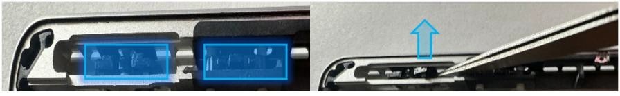
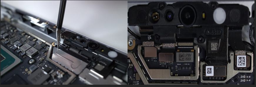
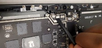
Remove Shields – Using ESD-Safe Tweezers, remove the two shields covering the camera FPCs by lifting from the corners shown.
Surface Pro 11th & 10th Edition for Business
Surface Pro for Business 11th Edition with Intel Only
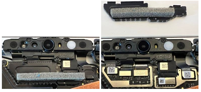
Disconnect Camera FPCs - Using the flat end of the Nylon spudger, gently disconnect 3 of the FPCs from the Motherboard.
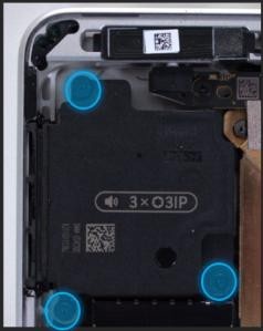
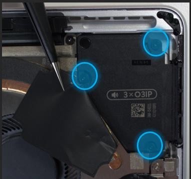
- Remove Microphone Module Screws – Using a 3IP (Torx-plus)
Driver, remove the 4 screws (
 ) on the Microphone Module. Once removed, carefully lift the
Microphone Module out of the device Enclosure. Don't touch the
front camera lens.
) on the Microphone Module. Once removed, carefully lift the
Microphone Module out of the device Enclosure. Don't touch the
front camera lens.

- Thermal Putty Cleanup – Clean the light blue/green putty as shown with IPA and cleaning swabs until the area is free of any residual T-Putty.
Procedure - Installation (Microphone Module)
- Apply Thermal Putty – Using the syringe of Thermal Putty, squeeze out approximately half of a tic mark of putty from the syringe.
- Install the Microphone Module – Place the new Microphone Module
into the corresponding Enclosure gap ensuring the holes in the
Microphone Module are in alignment with the Enclosure. Using a 3IP
(Torx- plus) Driver, install the 4 screws from the bag labeled
until finger tight, then adjust each of them with an more
1/8th turn (45-degrees) until secure Fasten them in the order shown
.
- Reconnect the Camera FPCs – Using your fingers, or the flat end of a Nylon Spudger, reconnect the 3FPCs to the corresponding connectors on the Motherboard.
- Apply new Shields – Using your fingers, assisted with the flat end of a Nylon Spudger, gently apply two new shields to cover the Camera FPCs. Using a finger, press on the edges to ensure a solid connection is made.

 Surface Pro 11th & 10th Edition for Business Surface Pro for Business 11th Edition with Intel
5. Install the Thermal Module + Fan – Apply new thermal pads to the
thermal module or motherboard and place thermal module on top.
Fasten 14 screws labeled with
,
,
,
on the bags and reconnect the FPC to the motherboard. Apply a new VC
tape to the thermal module. Refer to the Procedure – Installation (Thermal Module + Fan)
section for detailed instructions.
Surface Pro 11th & 10th Edition for Business Surface Pro for Business 11th Edition with Intel
5. Install the Thermal Module + Fan – Apply new thermal pads to the
thermal module or motherboard and place thermal module on top.
Fasten 14 screws labeled with
,
,
,
on the bags and reconnect the FPC to the motherboard. Apply a new VC
tape to the thermal module. Refer to the Procedure – Installation (Thermal Module + Fan)
section for detailed instructions.
- Install the Button PCB – Install the button PCB and secure with
2 screws (
). Assemble the tape and foam (VC gasket - 13NL-5LU0D11) spreading
across the button board and thermal module. Refer to the
Procedure – Installation (Buttons) section for detailed
instructions.
- Install the Surface Connect Port – Apply the new Surface Connect
PSA on the cable. Insert the cable into the enclosure and connect it
to the motherboard. Secure with 2 screws (
) . Refer to the
Procedure – Installation (Surface Connect Port) section for
detailed instructions.
- Install the Display Module - Install 2 new NFC foams. Reconnect the display FPC and install a new shield and shield tape on top. Align new PSA strips and install new speaker meshes on the display. Align the display on the bottom edge and press onto device. Use bonding frame tool to apply weight. Refer to the Procedure – Installation (Display Module) section for detailed instructions.
- Install the Removable Solid-State Drive – Turn the device over,
reinstall the solid-state drive and fasten a new screw from the bag
labeled
. Refer to the Procedure – Installation (Removable Solid-State Drive)
section for detailed instructions.
- Install the Removable Solid-State Drive Door – Refer to the Procedure – Installation (Solid-State Drive Door) section for detailed instructions.
- Power on device – Carefully place device screen side up. Connect the device to a power supply, open display, and power on to the Windows desktop screen.
- Run the Surface Diagnostic Toolkit (SDT) - Run SDT’s full diagnostic test to ensure device functions as expected.
- Power down device – Power down device using the OS start menu.
Rear Camera Replacement Process
Preliminary Requirements
Important
Be sure to follow all special (bolded) notes of caution within each process section.
Required Tools
- 3IP (Torx-plus) driver
- Anti-static wrist strap (1 MOhm resistance)
- Microfiber / Lint free cloth
- Soft ESD-safe mat
- Isopropyl alcohol (91 % or greater IPA)
- Cleaning swab
- USB drive with Surface Diagnostic Toolkit
- Nylon Spudger
- Plastic Opening pick
- Two 2-in spring clamps
- Metric ruler
- Fine tipped marker
- 3mm Allen Driver
- Foam Pad (see the Tools section for specifics)
- Display bonding weights (see the Tools section for specifics)
- Surface Display Debonding Tool (M1214770-001) - iFixit
- Surface Display Bonding Frame (M1260233-001) - iFixit
- ESD-safe Surface Battery Cover - iFixit
Primary Components
- Rear Camera (Refer to Illustrated Service Parts List)
- Surface Pro 11th & 10th Edition for Business
- 2 x M1.2*L1.3 3IP (Rear Camera screws),

- Part Number - 13NL-5LN0901/03
- 4 x M1.2*L2.7 3IP (Mic deck screws),
- Part Number - 13NL-5LN0E01/03
- 8 x M1.4*L1.9 3IP (Thermal Module screws),
- Part Number – 13NL-5JN0Z01/02
- 1 x M1.4*L2 3IP (Fan Screw),
- Part Number – 13NL-5JN1111/12
- 1 x M1.6*L2.9 3IP (Battery side screw),
- Part Number – 13NL-5LN1001/03
- 4 x M1.2*1.8L 3IP (CPU Bracket screws),
- Part Number – 13NL-5EU1K01/02
- 2 x M1.4*L1,9 3IP (Button PCBA Screws),
- Part Number - 13NL-5LN0B01/03
- 2 x (M1.4 X 0.3 x 1.7) (Surface Connect Screws),
- Part Number – 13NL-5JN1M01/02
- 1 x M 1.2 * L1.5 3IP (SSD Screw),
- Part Number – 13NL-5JN0V01/02
- 1 x Camera Shield Lid – 13NL-5LN0721
- 1 x Camera Shield Lid – 13NL-5LN0K01
- 1 x T-putty Syringe - 1330-00360QS
- 1 x Surface Connect PSA – 13NL-5JU2Z01
- 1 x VC gasket – 13NL-5LU0D11
- 1 x VC gasket (OLED) – 13NL-5MU0L21
- 1 x VC tape – 13NL-5LU0E11
- 1 x VC tape (OLED) – 13NL-5MU0K21
- 1 x TDM Shield lid – 13NL-5LN0H01
- 1 x TDM PSA Top – 13NL-5LUA41/43
- 1 x TDM PSA Right – 13NL-5LU0441/43
- 1 x TDM PSA Left – 13NL-5LU0741/43
- 1 x TDM PSA Bottom – 13NL-5LU0961/63
- 1 x Left Speaker Mesh – 13NL-5LU0532/33
- 1 x Right Speaker Mesh – 13NL-5LU0842/43
- 2 x Shielding tape – 13NL-5JU1501/02
- 2 x NFC foam – 13NL-5MU1A011 x T-putty Syringe - 1330-00360QS
- 1 x Right Speaker Mesh – 13NL-5LU0843
- 2 x Shielding tape – 13NL-5JU1502
- 2 x NFC foam – 13NL-5MU1A01
- 1 x CPU Pad – 13NL-5MU0Z01
- 2 x M1.2*L1.3 3IP (Rear Camera screws),
- Surface Pro for Business 11th Edition with Intel
- 1 x Rear Facing Camera
- Part Number - 70NL5M1Q1001
- 2 x M1.2*L1.3 3IP (Rear Camera screws),
- Part Number - 13NL-5LN0901/03
- 4 x M1.2*L2.7 3IP (Mic deck screws),
- Part Number - 13NL-5LN0E01/03
- 1 x M 1.2 * L1.5 3IP (SSD Screw),
- Part Number – 13NL-5JN0V01/02
- 1 x T4 Camera Shield Lid – 13NL-5MN0711
- 1 x T5 Camera Shield Lid – 13NL-5MN0901
- T4/T5 Camera Shield Foam LCD - 13NL-5QU0711
- T4/T5 Camera Shield Foam OLED - 13NL-5QU0811
- 2 x Deck Mesh - 13NL-5JU2T01
- 1 x T-putty Syringe - 1330-00360QS
- 1 x TDM Shield lid – 13NL-5QN1311
- 1 x TDM PSA Top – 13NL-5LUA41/43
- 1 x TDM PSA Right – 13NL-5LU0441/43
- 1 x TDM PSA Left – 13NL-5LU0741/43
- 1 x TDM PSA Bottom – 13NL-5LU0961/63
- 1 x Left Speaker Mesh – 13NL-5LU0532/33
- 1 x Right Speaker Mesh – 13NL-5LU0842/43
- 1 x Shielding tape – 13NL-5QU0P13/14
- 2 x NFC foam – 13NL-5MU1A01
- 1 x Rear Facing Camera
Additional Components (Ordered Separately)
- N/A
Procedure - Removal (Rear Camera)
- Remove the Removable Solid-State Drive Door – Refer to the Procedure – Removal (Solid-State Drive section for detailed instructions.
- Remove the Removable Solid-State Drive - Remove 1 screw and remove the rSSD. Refer to the Procedure – Removal (Removable Solid-State Drive) section for detailed instructions.
- Remove the Display Module – Using the Surface Debonding Tool, debond the display. Remove 1 shielding tape, 2 NFC foams and 1 shield lid and disconnect the FPC. Refer to the Procedure – Removal (Display Module) section for detailed instructions.
- Remove the Surface Connect Port Cable – Surface Pro 11th & 10th
Edition for Business Only: Remove 2 screws (
) and peel the Surface
Connect off the thermal module. Refer to the Procedure – Removal (Surface Connect Port) section for detailed
instructions.
- Remove the Button PCB – Surface Pro 11th & 10th Edition for
Business Only: Remove 2 screws (
) and the tape and foam spreading across the button board and
thermal module. Remove the button board from the device but leave the buttons in place. Refer to
the Procedure – Removal (Buttons) section for detailed instructions.
- Remove the Thermal Module + Fan – Surface Pro 11th & 10th
Edition for Business Only: Disconnect FPC, remove 14 screws (
and
) and carefully lift the thermal module out of the device. Refer to
the Procedure – Removal (Thermal Module + Fan) section for
detailed instructions.
- Remove the Microphone Module – Disconnect 3 FPCs and remove 4
screws (
). Refer to the Procedure- Removal (Microphone Module) section for detailed instructions.
- Disconnect the rear camera FPC – Using the flat end of the Nylon spudger, gently disconnect the FPC from the Motherboard

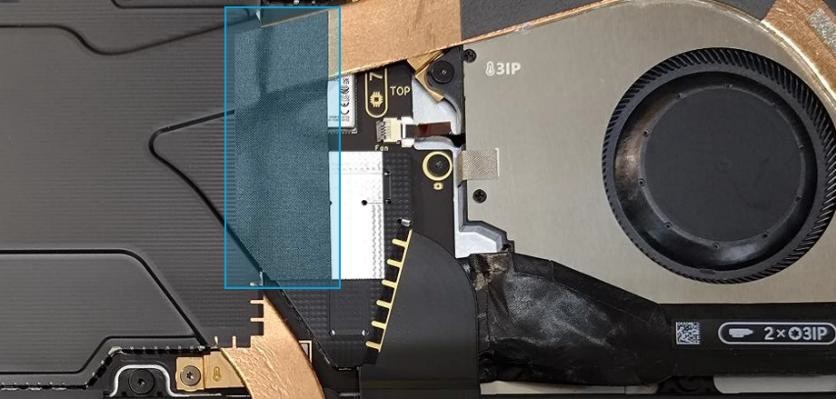
- Remove Rear Camera Screws – Using a 3IP (Torx-plus) Driver,
remove the 2 screws (
) outlined in the photo. Once removed, lift the Rear Camera
out of the enclosure.

Procedure - Installation (Rear Camera)
- Install the Rear Camera – Install the new rear camera into the
enclosure ensuring all holes are aligned. Once installed, use a 3IP
(Torx-plus) Driver to install 2 screws from the bag labeled
until finger tight, then adjust each an more 1/8th turn
(45-degrees) until snug.
Connect the Camera FPC – Using your fingers, or the flat end of a Nylon Spudger, connect the Camera FPC to the connector on the Motherboard.
Install the Microphone Module – Install 4 screws (
) and connect 3 FPCs. Refer to the Procedure – Installation (Microphone Module) section for detailed
instructions.Install the Thermal Module + Fan – Apply new thermal pads to the thermal module or motherboard and place thermal module on top. Fasten 14 screws labeled with
,
,
,
on the bags and reconnect the FPC to the motherboard. Apply a new VC
tape to the thermal module. Refer to the Procedure – Installation (Thermal Module + Fan)
section for detailed instructions.Install the Button PCB – Install the button PCB and secure with 2 screws (
). Assemble the tape and foam (VC gasket - 13NL-5LU0D11) spreading
across the button board and thermal module. Refer to the
Procedure – Installation (Buttons) section for detailed
instructions.Install the Surface Connect Port – Apply the new Surface Connect PSA on the cable. Insert the cable into the enclosure and connect it to the motherboard. Secure with 2 screws (
). Refer to the
Procedure – Installation (Surface Connect Port) section for
detailed instructions.Install the Display Module - Install 2 new NFC foams. Reconnect the display FPC and install a new shield and shield tape on top. Align new PSA strips and install new speaker meshes on the display. Align the display on the bottom edge and press onto device. Use bonding frame tool to apply weight. Refer to the Procedure – Installation (Display Module) section for detailed instructions.
Install the Removable Solid-State Drive – Turn the device over, reinstall the solid-state drive and fasten a new screw from the bag labeled
. Refer to the Procedure – Installation (Removable Solid-State Drive)
section for detailed instructions.Install the Removable Solid-State Drive Door – Refer to the Procedure – Installation (Solid-State Drive Door) section for detailed instructions.
Power on device – Carefully place device screen side up. Connect the device to a power supply, open display, and power on to the Windows desktop screen.
Run the Surface Diagnostic Toolkit (SDT) - Run SDT’s full diagnostic test to ensure device functions as expected.
Power down device – Power down device using the OS start menu
Front Camera Replacement Process
Preliminary Requirements
Important
Be sure to follow all special (bolded) notes of caution within each process section.
Required Tools
- 3IP (Torx-plus) driver
- Anti-static wrist strap (1 MOhm resistance)
- Microfiber / Lint free cloth
- Soft ESD-safe mat
- Isopropyl alcohol (91 % or greater IPA)
- Cleaning swab
- USB drive with Surface Diagnostic Toolkit
- Nylon Spudger
- Plastic Opening pick
- Two 2-in spring clamps
- Metric ruler
- Fine tipped marker
- 3mm Allen Driver
- Foam Pad (see the Tools section for specifics)
- Display bonding weights (see the Tools section for specifics)
- Surface Display Debonding Tool (M1214770-001) - iFixit
- Surface Display Bonding Frame (M1260233-001) - iFixit
- ESD-safe Surface Battery Cover - iFixit
Primary Components
- Front Camera (Refer to Illustrated Service Parts List)
- Surface Pro 11th & 10th Edition for Business
- 1 x Camera PSA – 13NL-5MU1211
- 4 x M1.2*L2.7 3IP (Mic deck screws),
- Part Number - 13NL-5LN0E01/03
- 8 x M1.4*L1.9 3IP (Thermal Module screws),
- Part Number – 13NL-5JN0Z01/02
- 1 x M1.4*L2 3IP (Fan Screw),
- Part Number – 13NL-5JN1111/12
- 1 x M1.6*L2.9 3IP (Battery side screw),
- Part Number – 13NL-5LN1001/03
- 4 x M1.2*1.8L 3IP (CPU Bracket screws),
- Part Number – 13NL-5EU1K01/02
- 2 x M1.4*L1,9 3IP (Button PCBA Screws),
- Part Number - 13NL-5LN0B01/03
- 2 x (M1.4 X 0.3 x 1.7) (Surface Connect Screws),
- Part Number – 13NL-5JN1M01/02
- 1 x M 1.2 * L1.5 3IP (SSD Screw),
- Part Number – 13NL-5JN0V01/02
- 1 x Camera Shield Lid – 13NL-5LN0721
- 1 x Camera Shield Lid – 13NL-5LN0K01
- 1 x T-putty Syringe - 1330-00360QS
- 1 x Surface Connect PSA – 13NL-5JU2Z01
- 1 x VC gasket – 13NL-5LU0D11
- 1 x VC gasket (OLED) – 13NL-5MU0L21
- 1 x VC tape – 13NL-5LU0E11
- 1 x VC tape (OLED) – 13NL-5MU0K21
- 1 x TDM Shield lid – 13NL-5LN0H01
- 1 x TDM PSA Top – 13NL-5LUA41/43
- 1 x TDM PSA Right – 13NL-5LU0441/43
- 1 x TDM PSA Left – 13NL-5LU0741/43
- 1 x TDM PSA Bottom – 13NL-5LU0961/63
- 1 x Left Speaker Mesh – 13NL-5LU0532/33
- 1 x Right Speaker Mesh – 13NL-5LU0842/43
- 2 x Shielding tape – 13NL-5JU1501/02
- 2 x NFC foam – 13NL-5MU1A01
- 1 x CPU Pad – 13NL-5MU0Z01
- Surface Pro for Business 11th Edition with Intel
- 1 x Front Camera Module -70NL5M1Q4000
- 1 x Camera PSA – 13NL-5MU1211
- 4 x M1.2*L2.7 3IP (Mic deck screws),
- Part Number - 13NL-5LN0E01/03
- 1 x M 1.2 * L1.5 3IP (SSD Screw),
- Part Number – 13NL-5JN0V01/02
- 1 x T4 Camera Shield Lid – 13NL-5MN0711
- 1 x T5 Camera Shield Lid – 13NL-5MN0901
- T4/T5 Camera Shield Foam LCD - 13NL-5QU0711
- T4/T5 Camera Shield Foam OLED - 13NL-5QU0811
- 2 x Deck Mesh - 13NL-5JU2T01
- 1 x T-putty Syringe - 1330-00360QS
- 1 x TDM Shield lid – 13NL-5QN1311
- 1 x TDM PSA Top – 13NL-5LUA41/43
- 1 x TDM PSA Right – 13NL-5LU0441/43
- 1 x TDM PSA Left – 13NL-5LU0741/43
- 1 x TDM PSA Bottom – 13NL-5LU0961/63
- 1 x Left Speaker Mesh – 13NL-5LU0532/33
- 1 x Right Speaker Mesh – 13NL-5LU0842/43
- 1 x Shielding tape – 1 x Shielding tape – 13NL-5QU0P13/14
- 2 x NFC foam – 13NL-5MU1A01
Additional Components (Ordered Separately)
- N/A
Procedure - Removal (Front Camera)
- Remove the Removable Solid-State Drive Door – Refer to the Procedure – Removal (Solid-State Drive section for detailed instructions.
- Remove the Removable Solid-State Drive - Remove 1 screw and remove the rSSD. Refer to the Procedure – Removal (Removable Solid-State Drive) section for detailed instructions.
- Remove the Display Module – Using the Surface Debonding Tool, debond the display. Remove 1 shielding tape, 2 NFC foams and 1 shield lid and disconnect the FPC. Refer to the Procedure – Removal (Display Module) section for detailed instructions.
- Remove the Surface Connect Port Cable – Surface Pro 11th & 10th
Edition for Business Only: Remove 2 screws (
) and peel the Surface
Connect off the thermal module. Refer to the Procedure – Removal (Surface Connect Port) section for detailed
instructions.
- Remove the Button PCB – Surface Pro 11th & 10th Edition for
Business Only: Remove 2 screws (
) and the tape and foam spreading across the button board and
thermal module. Remove the
button board from the device but leave the buttons in place. Refer to
the Procedure – Removal (Buttons)
section for detailed instructions.
- Remove the Thermal Module + Fan – Surface Pro 11th & 10th
Edition for Business Only: Disconnect FPC, remove 14 screws (
and
) and carefully lift the thermal module out of the device. Refer to
the Procedure – Removal (Thermal Module + Fan) section for
detailed instructions.
- Remove the Microphone Module – Disconnect 3 FPCs and remove 4
screws (
). Refer to the Procedure- Removal (Microphone Module) section for detailed instructions.
- Disconnect the Front Camera FPC – Using a Nylon spudger, disconnect the front camera from the motherboard.

- Remove the Front Facing Camera (Re-use only) – Install the camera cover (13NL-5LU1301) on the lens. Using the flat end of the plastic opening tool, position the tool under the right side of the FPC, and carefully lift to peel the camera off the enclosure.

- Remove the Front Facing Camera – Using the flat end of the plastic opening tool, position the tool under the FPC and lift to peel the camera off the enclosure.
- Clean PSA – Using tweezers or the Nylon spudger, remove the old PSA from the bucket and/or the camera. Clean the bucket area with IPA and cleaning swabs.
Procedure - Installation (Front Camera)
Install the Front Facing Camera PSA – Remove the bottom liner from the camera and stick the PSA onto the enclosure. The holes on the PSA liner align with the pins on the enclosure. Don't remove the top liner yet and press on the PSA with your finger. Hold the PSA down firmly for 10 seconds.

Install the Front Facing Camera – Remove the top liner from the PSA on the enclosure and camera. Using tweezers to handle the camera, install the camera by lining up the pin holes. Hold the camera down firmly for 10 seconds. Remove the camera cover when finished.
Connect the Front Facing Camera FPC – Using your fingers, or the flat end of a Nylon Spudger, press the Front Facing Camera FPC into the connector on the Motherboard.
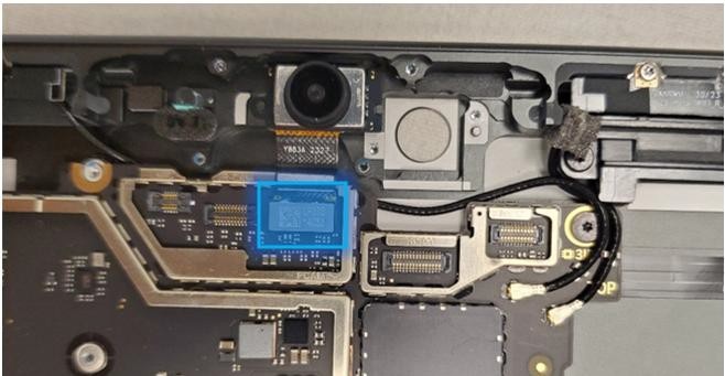
- Clean the camera – Using a microfiber cloth, clean the lens before installing microphone module.
- Install the Microphone Module – Install 4 screws (
) and connect 3 FPCs. Refer to the Procedure – Installation (Microphone Module) section for detailed
instructions.
- Install the Thermal Module + Fan – Apply new thermal pads to the
thermal module or motherboard and place thermal module on top.
Fasten 14 screws labeled with
,
,
,
on the bags and reconnect the FPC to the motherboard. Apply a new VC
tape to the thermal module. Refer to the Procedure – Installation (Thermal Module + Fan)
section for detailed instructions.
- Install the Button PCB – Install the button PCB and secure with
2 screws (
). Assemble the tape and foam (VC gasket - 13NL-5LU0D11) spreading
across the button board and thermal module. Refer to the
Procedure – Installation (Buttons) section for detailed
instructions.
- Install the Surface Connect Port – Apply the new Surface Connect
PSA on the cable. Insert the cable into the enclosure and connect it
to the motherboard. Secure with 2 screws (
). Refer to the
Procedure – Installation (Surface Connect Port) section for
detailed instructions.
- Install the Display Module - Install 2 new NFC foams. Reconnect the display FPC and install a new shield and shield tape on top. Align new PSA strips and install new speaker meshes on the display. Align the display on the bottom edge and press onto device. Use bonding frame tool to apply weight. Refer to the Procedure – Installation (Display Module) section for detailed instructions.
- Install the Removable Solid-State Drive – Turn the device over,
reinstall the solid-state drive and fasten a new screw from the bag
labeled
. Refer to the Procedure – Installation (Removable Solid-State Drive)
section for detailed instructions.
- Install the Removable Solid-State Drive Door – Refer to the Procedure – Installation (Solid-State Drive Door) section for detailed instructions.
- Power on device – Carefully place device screen side up. Connect the device to a power supply, open display, and power on to the Windows desktop screen.
- Run the Surface Diagnostic Toolkit (SDT) - Run SDT’s full diagnostic test to ensure device functions as expected.
- Power down device – Power down device using the OS start menu.
Battery Replacement Process
Preliminary Requirements
Important
Be sure to follow all special (bolded) notes of caution within each process section.
Required Tools
- 3IP (Torx-plus) driver
- Anti-static wrist strap (1 MOhm resistance)
- Microfiber / Lint free cloth
- Soft ESD-safe mat
- Isopropyl alcohol (91 % or greater IPA)
- Cleaning swab
- USB drive with Surface Diagnostic Toolkit
- Nylon Spudger
- Plastic Opening pick
- Two 2-in spring clamps
- Metric ruler
- Fine tipped marker
- 3mm Allen Driver
- Foam Pad (see the Tools section for specifics)
- Display bonding weights (see the Tools section for specifics)
- Surface Display Debonding Tool (M1214770-001) - iFixit
- Surface Display Bonding Frame (M1260233-001) - iFixit
- ESD-safe Surface Battery Cover - iFixit
Primary Components
- Battery (Refer to Illustrated Service Parts List)
- Surface Pro 11th & 10th Edition for Business
- 8 x M1.6*L1.8 4IP (Battery Frame),

- Part Number – 13NL-5LN0A01/03
- 1 x M1.6*L2.9 3IP (Battery FPC screw),

- Part Number – 13NL-5LN0V01/03
- 8 x M1.4*L1.9 3IP (Thermal Module screws),
- Part Number – 13NL-5JN0Z01/02
- 1 x M1.4*L2 3IP (Fan Screw),
- Part Number – 13NL-5JN1111/12
- 1 x M1.6*L2.9 3IP (Battery side screw),
- Part Number – 13NL-5LN1001/03
- 4 x M1.2*1.8L 3IP (CPU Bracket screws),
- Part Number – 13NL-5EU1K01/02
- 2 x M1.4*L1,9 3IP (Button PCBA Screws),
- Part Number - 13NL-5LN0B01/03
- 2 x (M1.4 X 0.3 x 1.7) (Surface Connect Screws),
- Part Number – 13NL-5JN1M01/02
- 1 x M 1.2 * L1.5 3IP (SSD Screw),
- Part Number – 13NL-5JN0V01/02
- 1 x Surface Connect PSA – 13NL-5JU2Z01
- 1 x VC gasket – 13NL-5LU0D11
- 1 x VC gasket (OLED) – 13NL-5MU0L21
- 1 x VC tape – 13NL-5LU0E11
- 1 x VC tape (OLED) – 13NL-5MU0K21
- 1 x TDM Shield lid – 13NL-5LN0H01
- 1 x TDM PSA Top – 13NL-5LUA41/43
- 1 x TDM PSA Right – 13NL-5LU0441/43
- 1 x TDM PSA Left – 13NL-5LU0741/43
- 1 x TDM PSA Bottom – 13NL-5LU0961/63
- 1 x Left Speaker Mesh – 13NL-5LU0532/33
- 1 x Right Speaker Mesh – 13NL-5LU0842/43
- 2 x Shielding tape – 13NL-5JU1501/02
- 1 x CPU Pad – 13NL-5MU0Z01
- 2 x NFC foam – 13NL-5MU1A01
- 8 x M1.6*L1.8 4IP (Battery Frame),
- Surface Pro for Business 11th Edition with Intel
- 1 x Battery Module
- Part Number OLED – M1273534-003
- Part Number LCD – M1236934-009
- 8 x M1.6*L1.8 4IP (Battery Frame),
- Part Number – 13NL-5LN0A01/03
- 1 x M1.6*L2.9 3IP (Battery FPC screw),
- Part Number – 13NL-5LN0V01/03
- 6 x M1.4*L1.9 3IP (Thermal Module screws),
- Part Number – 13NL-5JN0Z01/02
- 1 x M1.4*L2 3IP (Fan Screw),
- Part Number – 13NL-5JN1111/12
- 1 x M1.6*L2.9 3IP (Battery side screw),
- Part Number – 13NL-5LN1001/03
- 4 x M1.2*1.8L 3IP (CPU Bracket screws),
- Part Number – 13NL-5EU1K01/02
- 2 x (M1.4 X 0.3 x 1.7) (Surface Connect Screws),
- Part Number – 13NL-5JN1M01/02
- 1 x M 1.2 * L1.5 3IP (SSD Screw),
- Part Number – 13NL-5JN0V01/02
- 1 x Surface Connect PSA – 13NL-5JU2Z01
- 1 x T1 gasket LCD - 13NL-5QU0X03/04
- 1 x T1 gasket OLED - 13NL-5QU0Y03/04
- 1 x T1 Shield Lid – 13NL-5QN0X01
- 1 x TDM Shield lid – 13NL-5QN1311
- 1 x TDM PSA Top – 13NL-5LUA41/43
- 1 x TDM PSA Right – 13NL-5LU0441/43
- 1 x TDM PSA Left – 13NL-5LU0741/43
- 1 x TDM PSA Bottom – 13NL-5LU0961/63
- 1 x Left Speaker Mesh – 13NL-5LU0532/33
- 1 x Right Speaker Mesh – 13NL-5LU0842/43
- 1 x Shielding tape – 13NL-5QU0P13/14
- 2 x NFC foam – 13NL-5MU1A01
- 1 x Battery Module
Additional Components (Ordered Separately)
- N/A
Procedure - Preparation (Battery)
Important
This section is only for instances where you're replacing the battery. If the battery is being re- used, then this section isn't required.
- Connect USB – Connect USB with the Surface Diagnostic Toolkit (SDT) loaded to an available USB port on the device under repair.
- Power on device – Connect a power supply to the device. Press the power button on the device to power on the device. Allow it to boot to the Windows Desktop before continuing.
- Launch SDT – From the Windows Desktop, use Windows Explorer to navigate to the USB drive. Select the SDT executable (.exe) to launch the Surface Diagnostic Toolkit.
- Run Battery Repair (Setup) – From the SDT launch screen, select Repair from the drop-down menu. Next, select Repair Setup and Validation to enter the selection screen. Run the Battery Repair (Setup) to put your device into repair mode. Follow all on-screen instructions and allow the device to shut down when prompted. Disconnect the Power Supply and remove the USB drive before proceeding forward.
Procedure - Removal (Battery)
- Remove the Removable Solid-State Drive Door – Refer to the Procedure – Removal (Solid-State Drive section for detailed instructions.
- Remove the Removable Solid-State Drive - Remove 1 screw and remove the rSSD. Refer to the Procedure – Removal (Removable Solid-State Drive) section for detailed instructions.
- Remove the Display Module – Using the Surface Debonding Tool, debond the display. Remove 1 shielding tape, 2 NFC foams and 1 shield lid and disconnect the FPC. Refer to the Procedure – Removal (Display Module) section for detailed instructions.
Important
Verify the battery’s condition. Devices exhibiting battery issues as outlined in the Lithium-Ion Battery Inspection section require replacement of the entire device.
- Remove the Surface Connect Port Cable – Remove 2 screws (
) and peel the Surface
Connect off the thermal module. Refer to the Procedure – Removal (Surface Connect Port) section for detailed instructions.
- Remove the Button PCB – Remove 2 screws (
) and the tape and foam spreading across the button board and
thermal module. Remove the button board from the device but leave
the buttons in place. Refer to the Procedure – Removal (Buttons) section for detailed
instructions.
- Remove the Thermal Module + Fan – Disconnect FPC, remove 14
screws (
and
) and carefully lift the thermal module out of the device. Refer to
the Procedure – Removal (Thermal Module + Fan) section for
detailed instructions.
- Disconnect battery connector – Using a Nylon Spudger, disconnect the battery connector from the Motherboard.
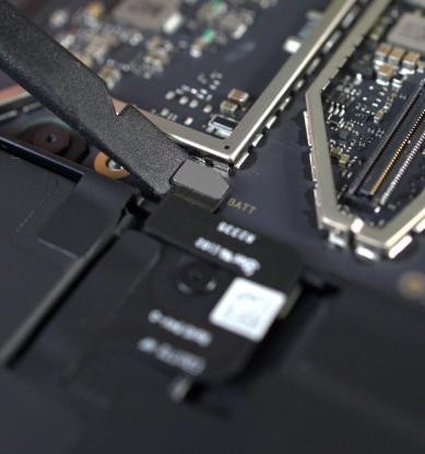
- Remove the Battery Screws – Remove the 9 screws from the Battery frame using a 3IP (Torx-plus) driver.
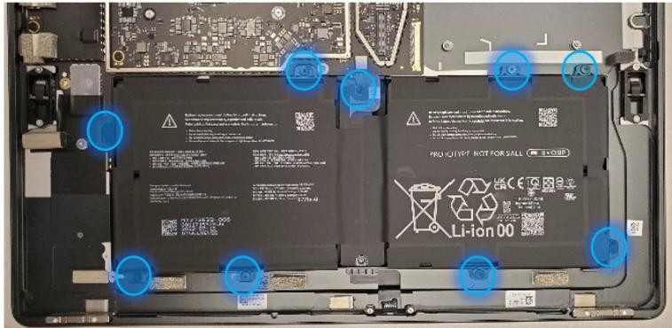
- Lift out the Battery – Using two gloved hands, grab the battery by the frame at the points identified in the photo and gently lift the battery out of the enclosure. Set battery on a clean, ESD-safe, flat surface. If reusing the original battery in the case of an enclosure replacement, lift and install the battery directly into the new enclosure after inspecting the device for any foreign objects and screws.
Warning
In the instance of a battery event, completely submerge the entire device in a 1-gallon enclosure filled with 0.5 gallons of clean sand, use a fire blanket, or a fire extinguisher. DO NOT attempt to pick up the device.
Warning
Only handle the battery by the plastic frame. Bending, twisting, or impacting the battery might damage the battery, damage the device, and/or result in severe personal injury or property damage. Always use two hands when handling the battery.
Important
Place the battery somewhere where the battery can't accidentally be contacted or damaged. DO NOT place anything on top of the battery.
Important
When disposing of the battery, ensure you're recycling according to local laws.
Important
The Motherboard and Battery are sensitive to ESD and can be easily damaged. It's critical that you ensure proper grounding before performing any work on these parts.
Procedure - Installation (Battery)
Important
Don't reuse the original battery except in the case of an Enclosure replacement. Use a new battery if the original battery has been damaged.
- Inspect the device – Check the Enclosure for any loose articles
that might be present. Perform the following actions:
- Check and remove any foreign objects that the magnets might have attracted.
- Pay special attention to the magnetized areas around the Enclosures edge.
- Verify all removed screws are accounted for and haven't been misplaced inside the device.
- Loose screws should never be stored on the magnetic areas of the Enclosure.
- Insert the new Battery – Carefully open the packaging of the battery. Pick up the battery using the handling loops and place it into the device. Align the holes so that the battery is set into place.
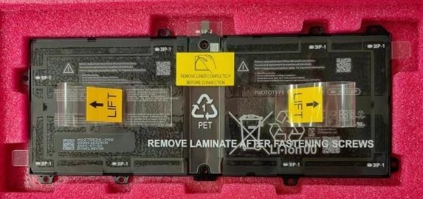
Warning
Only handle the new battery by the plastic loops. Bending, twisting, or impacting the battery might damage the battery, damage the device, and/or result in severe personal injury or property damage. Always use two hands when handling the battery.
- Install the Battery screws – Using a 3IP (Torx-plus) driver,
install the 8 Battery Frame screws (marked
 ) and the 1 Battery PCB screw (marked
  ) until finger right then tighten each by an more 1/8th turn
(45-degrees).
) until finger right then tighten each by an more 1/8th turn
(45-degrees).

Important
Be careful not to overtighten screws. If the Battery frame is cracked or the battery is damaged in any way during installation, it can't be used and must be replaced.
- Remove the liner – After all the screws have been seated, hold one of the tabs on the right or left of the Battery liner. Peel the handling liner away from the Battery. If working on other components, apply the ESD-safe Surface Battery Cover to ensure the Battery is protected.
- Connect Battery FPC – Connect the Battery FPC to the Motherboard by aligning the connector and gently pressing down with your finger, or the flat end of a Nylon Spudger.
Important
Be careful not to apply too much pressure on the connector. Too much pressure can damage the Motherboard or the Battery Connector requiring replacement of the damaged part.
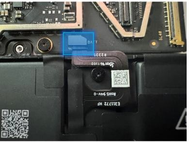
- Install the Thermal Module + Fan – Apply new thermal pads to the
thermal module or motherboard and place thermal module on top.
Fasten 14 screws labeled with
,
,
,
on the bags and reconnect the FPC to the motherboard. Apply a new VC
tape to the thermal module. Refer to the Procedure – Installation (Thermal Module + Fan)
section for detailed instructions.
- Install the Button PCB – – Install the button PCB and secure
with 2 screws (
). Assemble the tape and foam (VC gasket - 13NL-5LU0D11) spreading
across the button board and thermal module. Refer to the
Procedure – Installation (Buttons) section for detailed
instructions.
- Install the Surface Connect Port – Apply the new Surface Connect
PSA on the cable. Insert the cable into the enclosure and connect it
to the motherboard. Secure with 2 screws (
). Refer to the
Procedure – Installation (Surface Connect Port) section for
detailed instructions.
- Install the Display Module - Install 2 new NFC foams. Reconnect the display FPC and install a new shield and shield tape on top. Align new PSA strips and install new speaker meshes on the display. Align the display on the bottom edge and press onto device. Use bonding frame tool to apply weight. Refer to the Procedure – Installation (Display Module) section for detailed instructions.
- Install the Removable Solid-State Drive – Turn the device over,
reinstall the solid-state drive and fasten a new screw from the bag
labeled
. Refer to the Procedure – Installation (Removable Solid-State Drive)
section for detailed instructions.
- Install the Removable Solid-State Drive Door – Refer to the Procedure – Installation (Solid-State Drive Door) section for detailed instructions.
Procedure - Finalize (Battery)
- Power on Device – Connect a Power Supply to the device and power it on until it reaches the Windows Desktop.
- Connect USB – Connect USB with the Surface Diagnostic Toolkit (SDT) loaded to an available USB port on the device under repair.
- Launch SDT – From the Windows Desktop, use Windows Explorer to navigate to the USB drive. Select the SDT executable (.exe) to launch the Surface Diagnostic Toolkit.
- Allow the Battery to charge – With the device connected to a power supply, allow the battery to charge until the battery icon in Windows reads at least 50% remaining battery charge.
- Run Battery Authentication – From the SDT launch screen, select Repair from the drop-down menu. Next, select Repair Setup and Validation to enter the selection screen. Select the Battery Repair (Validation) tool and follow the on-screen prompts until a successful authentication is completed.
Important
Battery authentication requires a stable internet connection and the latest version of the Surface Management Extension. If the battery validation tool fails or isn't detected properly, install the Surface Management Extension, reboot the device, and try again with a new internet connection. If failures continue, reach out to Microsoft Support.
- Run the Surface Diagnostic Toolkit (SDT) – Run all diagnostics to ensure the device is functioning as expected before moving forward.
- Power down device – Power down device using the OS start menu.
Motherboard Replacement Process
Preliminary Requirements
Important
Replacing the motherboard might result in a different internal serial number for your device. This new serial number can be found in Settings/About and the Surface App under Device Information. The new serial number will also be updated in your account. For support, refer to the serial number on the device's external cover. More information: How to get service or repair for Surface - Microsoft Support. Be sure to follow all special (bolded) notes of caution within each process section.
Required Tools
- 3IP (Torx-plus) driver
- Anti-static wrist strap (1 MOhm resistance)
- Microfiber / Lint free cloth
- Soft ESD-safe mat
- Isopropyl alcohol (91 % or greater IPA)
- Cleaning swab
- USB drive with Surface Diagnostic Toolkit
- Nylon Spudger
- Plastic Opening pick
- Two 2-in spring clamps
- Metric ruler
- Fine tipped marker
- 3mm Allen Driver
- Foam Pad (see the Tools section for specifics)
- Display bonding weights (see the Tools section for specifics)
- Surface Display Debonding Tool (M1214770-001) - iFixit
- Surface Display Bonding Frame (M1260233-001) - iFixit
- ESD-safe Surface Battery Cover - iFixit
Primary Components
- Motherboard (Refer to Illustrated Service Parts List)
- Surface Pro 11th & 10th Edition for Business
- 5 x M1.4*L2 3IP (Motherboard Body and thermal module fan screws),
- 4 x
 and 1 x
- Part Number – 13NL-5JN1111/121 x M1.4*L1.65 3IP (M.2 connector
screw),

- Part Number – 13NL-5JN0X01/02
- 8 x M1.4*L1.9 3IP (Thermal Module screws),
- Part Number – 13NL-5JN0Z01/02
- 1 x M1.4*L2 3IP (Fan Screw),
- Part Number – 13NL-5JN1111/12
- 1 x M1.6*L2.9 3IP (Battery side screw),
- Part Number – 13NL-5LN1001/03
- 4 x M1.2*1.8L 3IP (CPU Bracket screws),
- Part Number – 13NL-5EU1K01/02
- 5 x M1.4*L1,9 3IP (Button PCBA and left speaker Screws)
- 2 x
and 3 x
- Part Number - 13NL-5LN0B01/03
- 2 x (M1.4 X 0.3 x 1.7) (Surface Connect Screws),
- Part Number – 13NL-5JN1M01/02
- 1 x M 1.2 * L1.5 3IP (SSD Screw),
- Part Number – 13NL-5JN0V01/02
- 1 x RF tape - 13NL-5JU0F31/32
- 1 x RF foam - 13NL-5JU1901/02
- 1 x Camera Shield Lid – 13NL-5LN0721
- 1 x Camera Shield Lid – 13NL-5LN0K01
- 1 x T-putty Syringe - 1330-00360QS
- 1 x Surface Connect PSA – 13NL-5JU2Z01
- 1 x VC gasket – 13NL-5LU0D11
- 1 x VC gasket (OLED) – 13NL-5MU0L21
- 1 x VC tape – 13NL-5LU0E11
- 1 x VC tape (OLED) – 13NL-5MU0K21
- 1 x TDM Shield lid – 13NL-5LN0H01
- 1 x TDM PSA Top – 13NL-5LUA41/43
- 1 x TDM PSA Right – 13NL-5LU0441/43
- 1 x TDM PSA Left – 13NL-5LU0741/43
- 1 x TDM PSA Bottom – 13NL-5LU0961/63
- 1 x Left Speaker Mesh – 13NL-5LU0532/33
- 1 x Right Speaker Mesh – 13NL-5LU0842/43
- 2 x Shielding tape – 13NL-5JU1501/02
- 1 x CPU Pad – 13NL-5MU0Z01
- 2 x NFC foam – 13NL-5MU1A01
- Surface Pro for Business 11th Edition with Intel
- 1 x Motherboard
- See part list
- 7 x M1.4*L2 3IP (Motherboard Body and thermal module fan screws),
- 6 x
and 1 x
- Part Number – 13NL-5JN1111/121
- 6 x M1.4*L1.9 3IP (Thermal Module screws),
- Part Number – 13NL-5JN0Z01/02
- M1.4*L1.65 3IP (M.2 connector screw),
- Part Number – 13NL-5JN0X01/02
- 1 x M1.4*L2 3IP (Fan Screw),
- Part Number – 13NL-5JN1111/12
- 1 x M1.6*L2.9 3IP (Battery side screw),
- Part Number – 13NL-5LN1001/03
- 4 x M1.2*1.8L 3IP (CPU Bracket screws),
- Part Number – 13NL-5EU1K01/02
- 5 x M1.4*L1,9 3IP (Button PCBA and left speaker Screws)
- 2 x
and 3 x
- Part Number - 13NL-5LN0B01/03
- 2 x (M1.4 X 0.3 x 1.7) (Surface Connect Screws),
- Part Number – 13NL-5JN1M01/02
- 1 x M 1.2 * L1.5 3IP (SSD Screw),
- Part Number – 13NL-5JN0V01/02
- THM Charger Pad – 13NL-5QU0W01
- CPU Pad – 13NL-5QU1101
- PMIC Pad – 13NL-5QU1301
- HP Pad - 13NL-5QU1201
- 1 x RF tape - 13NL-5LU1A01/13NL-5QU0S02
- 1 x RF foam - 13NL-5QU0D01/03
- 1 x T4 Camera Shield Lid – 13NL-5MN0711
- 1 x T5 Camera Shield Lid – 13NL-5MN0901
- T4/T5 Camera Shield Foam LCD - 13NL-5QU0713/14
- T4/T5 Camera Shield Foam OLED - 13NL-5QU0813/14
- 2 x Deck Mesh - 13NL-5JU2T01
- 1 x Surface Connect PSA – 13NL-5JU2Z01
- 1 x T1 gasket LCD - 13NL-5QU0X03/04
- 1 x T1 gasket OLED - 13NL-5QU0Y03/04
- 1 x T1 Shield Lid – 13NL-5QN0X01
- 1 x TDM Shield lid – 13NL-5QN1311
- 1 x TDM PSA Top – 13NL-5LUA41/43
- 1 x TDM PSA Right – 13NL-5LU0441/43
- 1 x TDM PSA Left – 13NL-5LU0741/43
- 1 x TDM PSA Bottom – 13NL-5LU0961/63
- 1 x Left Speaker Mesh – 13NL-5LU0532/33
- 1 x Right Speaker Mesh – 13NL-5LU0842/43
- 1 x Shielding tape – 13NL-5QU0P13/14
- 2 x NFC foam – 13NL-5MU1A01
- 1 x Motherboard
Additional Components (Ordered Separately)
- N/A
Procedure - Removal (Motherboard)
Remove the Removable Solid-State Drive Door – Refer to the Procedure – Removal (Solid-State Drive section for detailed instructions.
Remove the Removable Solid-State Drive - Remove 1 screw and remove the rSSD. Refer to the Procedure – Removal (Removable Solid-State Drive) section for detailed instructions.
Remove the Display Module – Using the Surface Debonding Tool, debond the display. Remove 1 shielding tape, 2 NFC foams and 1 shield lid and disconnect the FPC. Refer to the Procedure – Removal (Display Module) section for detailed instructions.
Remove the Surface Connect Port Cable – Remove 2 screws (
) and peel the Surface
Connect off the thermal module. Refer to the Procedure – Removal (Surface Connect Port) section for detailed instructions.Remove the Left Speaker – Remove 3 screws (
). Refer to the Procedure – Removal (Speakers) section for detailed
instructions.Remove the Button PCB – Remove 2 screws (
) and the tape and foam spreading across the button board and
thermal module. Remove the button board from the device but leave
the buttons in place. Refer to the Procedure – Removal (Buttons) section for detailed
instructions.Remove the Thermal Module + Fan – Disconnect FPC, remove 14 screws (
and
) and carefully lift the thermal module out of the device. Refer to
the Procedure – Removal (Thermal Module + Fan section for
detailed instructions.Remove Camera Shields and disconnect Camera FPCs – Using ESD-safe tweezers, remove the 2 shields covering the Camera FPCs by lifting each shield from the corners. Once removed, use the flat end of a Nylon Spudger to disconnect all 5 Camera FPCs from the Motherboard.
Surface Pro 11th & 10th Edition for Business

Surface Pro for Business 11th Edition with Intel Only
Disconnect Wireless Coax Cables and Battery FPC – Using the flat end of a plastic opening tool, disconnect the 2 coax cables from the motherboard. Using the flat end of a Nylon Spudger, disconnect the Battery FPC from the Motherboard.
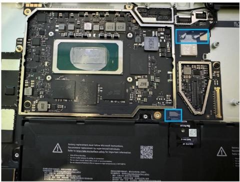
- Remove the RF foam and tape– Using ESD-safe Tweezers, lift and remove the foam and shielding tape from the area shown. These will be replaced with new ones.

Remove Motherboard screws – Using a 3IP (Torx-plus) driver, remove 5 (SP11 & SP10) or 7 (SP11 with Intel) Motherboard screws labeled with
 .
.Surface Pro 11th & 10th Edition for Business
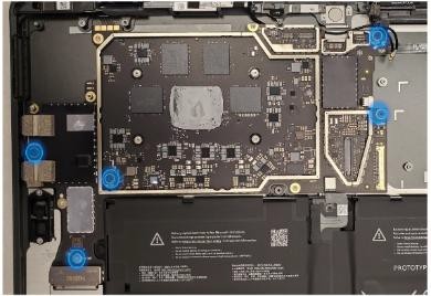
Surface Pro for Business 11th Edition with Intel

Lift the Motherboard out of the Enclosure – Using two hands, tilt the board to the left, and then pull the Motherboard out from the Enclosure. Ensure the USB connectors are free from the enclosure before fully removing the board to avoid damage. Don't damage the battery or cameras during disassembly.

Clean the enclosure – Using IPA and cleaning swabs, clean any residual tape from the enclosure. If reusing the motherboard, clean the main chip and tape area with IPA and cleaning swabs.
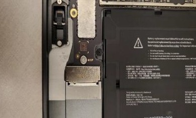
| Surface Pro 11th & 10th Edition for Business | Surface Pro for Business 11th Edition with Intel |
|---|

Procedure - Installation (Motherboard)
- Install the new Motherboard – Using two hands, insert the new motherboard so that the USB ports enter the open spots in the Enclosure. Once inserted, align the Motherboard with the screw bosses and holes. Ensure all connectors and cables are on top of the motherboard.
Important
Ensure all cables and connectors are on top of the Motherboard when installed before moving forward. Count: 5 FPCs for mic/cameras, 2 coax cables and 1 battery connector.
Install Motherboard screws – Using a 3IP (Torx-plus) driver, install the 4 (SP10 and SP11) or 6 (SP11 for Intel) Motherboard screws from the bag labeled
in the locations shown. Install 1 motherboard screw from the
bag labeled
.Surface Pro 11th & 10th Edition for Business

Surface Pro for Business 11th Edition with Intel

Reconnect the Battery Connector and 2 Wireless Coax cables – Using the flat-end of a Nylon Spudger, align the Battery FPC with its corresponding connector on the Motherboard and press down to complete the connection. Route the coax cables as shown and connect them to the motherboard. The coax cable from the left antenna board connects to the connector on the left, and the coax cable coming from the right antenna board connects to the motherboard on the right. The left antenna board coax cable will partially be under the motherboard as shown. Ensure alignment of the connectors before applying light pressure as the ports can be damaged requiring replacement of the Motherboard.

Reconnect the Camera FPCs – Using the flat end of a Nylon Spudger, align the 5 FPCs with their corresponding connector on the Motherboard. Press each down to complete the connection.
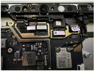
Install RF tape – Using your hands, or ESD-Safe Tweezers, place the tape near the bottom motherboard screw. Start by aligning the hole on the tape with the screw and carefully attaching the tape above and that area. Use the etching on the enclosure to help guide alignment.

- Install RF Foam on the RF tape – Place the Foam on top of the Shielding Tape. The top and left edges should align to the edges of the tape as shown.
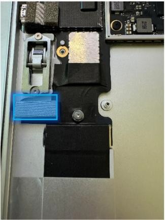
- Install the Thermal Module + Fan – – Apply new thermal pads to
the thermal module or motherboard and place thermal module on top.
Fasten 14 screws labeled with
,
,
,
on the bags and reconnect the FPC to the motherboard. Apply a new VC
tape to the thermal module. Refer to the Procedure – Installation (Thermal Module + Fan)
section for detailed instructions.
- Install the Button PCB – Install the button PCB and secure with
2 screws (
). Assemble the tape and foam (VC gasket - 13NL-5LU0D11) spreading
across the button board and thermal module Refer to the
Procedure – Installation (Buttons) section for detailed
instructions.
- Install the Left Speaker – Install the part with 3 screws (
). Refer to the Procedure – Installation section for
detailed instructions.
- Install the Surface Connect Port – Apply the new Surface Connect
PSA on the cable. Insert the cable into the enclosure and connect it
to the motherboard. Secure with 2 screws (
). Refer to the
Procedure – Installation (Surface Connect Port) section for
detailed instructions.
- Install the Display Module - - Install 2 new NFC foams. Reconnect the display FPC and install a new shield and shield tape on top. Align new PSA strips and install new speaker meshes on the display. Align the display on the bottom edge and press onto device. Use bonding frame tool to apply weight. Refer to the Procedure – Installation (Display Module) section for detailed instructions.
- Install the Removable Solid-State Drive – Turn the device over,
reinstall the solid-state drive and fasten a new screw from the bag
labeled
. Refer to the Procedure – Installation (Removable Solid-State Drive)
section for detailed instructions.
- Install the Removable Solid-State Drive Door – Refer to the Procedure – Installation (Solid-State Drive Door) section for detailed instructions.
Procedure - Finalize (Motherboard)
Important
If replacing both the Motherboard and the Display Module – complete the Motherboard replacement before performing the Display Module Replacement to ensure proper part operation.
- Power on Device – Connect a Power Supply to the device and power it on until it reaches the Windows Desktop.
- Connect USB – Connect USB with the Surface Diagnostic Toolkit (SDT) loaded to an available USB port on the device under repair.
- Launch SDT – From the Windows Desktop, use Windows Explorer to navigate to the USB drive. Select the SDT executable (.exe) to launch the Surface Diagnostic Toolkit.
- Run Touch Display Calibration – From the SDT launch screen, select Repair from the drop-down menu. Next, select Repair Setup and Validation to enter the selection screen. Run the Touch Display (Calibration) tool to calibrate the display. Follow all on-screen instructions and allow the device to restart when prompted.
Important
If the calibration fails, reboot the device, and try again. If the failure continues, then the display might be faulty and require replacement.
- Allow the Battery to charge – With the device connected to a power supply, allow the battery to charge until the battery icon in Windows reads at least 50% remaining battery charge.
- Launch SDT – Once the device has rebooted and is at the Windows Desktop, use Windows Explorer to navigate to the USB drive. Select the SDT executable (.exe) to launch the Surface Diagnostic Toolkit.
- Run Battery Authentication – From the SDT launch screen, select Repair from the drop-down menu. Next, select Repair Setup and Validation to enter the selection screen. Select the Battery Repair (Validation) tool to ensure the battery is detected as properly authenticated. If the battery reads anything other than authenticated, run the Validation tool in its entirety.
Important
Battery authentication requires a stable internet connection and the latest version of the Surface Management Extension. If the battery validation tool fails or isn't detected properly, install the Surface Management Extension, reboot the device, and try again with a new internet connection. If failures continue, reach out to Microsoft Support.
- Run the Surface Diagnostic Toolkit (SDT) – Run all diagnostics to ensure the device is functioning as expected before moving forward.
- Power down device – Power down device using the OS start menu.
Enclosure Replacement Process
Preliminary Requirements
Important
The replacement enclosure doesn't include the device’s serial number. In the event you need Microsoft support in the future, handwrite the original serial number on the label accompanied the part and affix to the completed label on the device. Be sure to follow all special (bolded) notes of caution within each process section.
Required Tools
- 3IP (Torx-plus) driver
- Anti-static wrist strap (1 MOhm resistance)
- Microfiber / Lint free cloth
- Soft ESD-safe mat
- Isopropyl alcohol (91 % or greater IPA)
- Cleaning swab
- USB drive with Surface Diagnostic Toolkit
- Nylon Spudger
- Plastic Opening pick
- Two 2-in spring clamps
- Metric ruler
- Fine tipped marker
- 3mm Allen Driver
- Foam Pad (see the Tools section for specifics)
- Display bonding weights (see the Tools section for specifics)
- Surface Display Debonding Tool (M1214770-001) - iFixit
- Surface Display Bonding Frame (M1260233-001) - iFixit
- ESD-safe Surface Battery Cover - iFixit
Primary Components
- Enclosure (Refer to Illustrated Service Parts List)
- Surface Pro 11th & 10th Edition for Business
- 6 x M1.2*2.7L 3IP (Antenna PCB screw),

- Part Number - 13NL-5LN0F01/03
- 8 x M1.6*L1.8 4IP (Battery Frame),
- Part Number – 13NL-5LN0A01/03
- 1 x M1.6*L2.9 3IP (Battery FPC screw),
- Part Number – 13NL-5LN0V01/03
- 5 x M1.4*L2 3IP (Motherboard Body and thermal module fan screws),
- 4 x
and 1 x
- Part Number – 13NL-5JN1111/12
- 1 x M1.4*L1.65 3IP (M.2 connector screw),
- Part Number – 13NL-5JN0X01/02
- 9 x M1.4*L1,9 3IP (Button PCBA and left speaker screws)
- 2 x
and 6 x
and 1 x fan duct (unmarked)
- Part Number - 13NL-5LN0B01/03
- 2 x M1.2*L1.3 3IP (Rear Camera screws),
- Part Number - 13NL-5LN0901/03
- 4 x M1.2*L2.7 3IP (Mic deck screws),
- Part Number - 13NL-5LN0E01/03
- 8 x M1.4*L1.9 3IP (Thermal Module screws),
- Part Number – 13NL-5JN0Z01/02
- 1 x M1.4*L2 3IP (Fan Screw),
- Part Number – 13NL-5JN1111/12
- 4 x M1.2*1.8L 3IP (CPU Bracket screws),
- Part Number – 13NL-5EU1K01/02
- 2 x (M1.4 X 0.3 x 1.7) (Surface Connect Screws),
- Part Number – 13NL-5JN1M01/02
- 1 x M 1.2 * L1.5 3IP (SSD Screw),
- Part Number – 13NL-5JN0V01/02
- 1 X Front Camera Cover - 13NL-5LU1301
- 1 x Fan duct foam - 13NL-5LU0B21/22
- 1 x RF tape - 13NL-5JU0F31/32
- 1 x RF foam - 13NL-5JU1901/02
- 1 x Camera Shield Lid – 13NL-5LN0721
- 1 x Camera Shield Lid – 13NL-5LN0K01
- 1 x T-putty Syringe - 1330-00360QS
- 1 x Surface Connect PSA – 13NL-5JU2Z01
- 1 x VC gasket – 13NL-5LU0D11
- 1 x VC gasket (OLED) – 13NL-5MU0L21
- 1 x VC tape – 13NL-5LU0E11
- 1 x VC tape (OLED) – 13NL-5MU0K21
- 1 x TDM Shield lid – 13NL-5LN0H01
- 1 x TDM PSA Top – 13NL-5LUA41/43
- 1 x TDM PSA Right – 13NL-5LU0441/43
- 1 x TDM PSA Left – 13NL-5LU0741/43
- 1 x TDM PSA Bottom – 13NL-5LU0961/63
- 1 x Left Speaker Mesh – 13NL-5LU0532/33
- 1 x Right Speaker Mesh – 13NL-5LU0842/43
- 2 x Shielding tape – 13NL-5JU1501/02
- 2 x NFC foam – 13NL-5MU1A01
- 1 x CPU Pad – 13NL-5MU0Z01
- 6 x M1.2*2.7L 3IP (Antenna PCB screw),
- Surface Pro for Business 11th Edition with Intel
- 6 x M1.2*2.7L 3IP (Antenna PCB screw),
- Part Number - 13NL-5LN0F01/03
- 8 x M1.6*L1.8 4IP (Battery Frame),
- Part Number – 13NL-5LN0A01/03
- 1 x M1.6*L2.9 3IP (Battery FPC screw),
- Part Number – 13NL-5LN0V01/03
- 7 x M1.4*L2 3IP (Motherboard Body and thermal module fan screws),
- 6 x
and 1 x
- Part Number – 13NL-5JN1111/121
- 1 x M1.4*L1.65 3IP (M.2 connector screw),
- Part Number – 13NL-5JN0X01/02
- 9 x M1.4*L1,9 3IP (Button PCBA and left speaker screws)
- 2 x
and 6 x
and 1 x fan duct (unmarked)
- Part Number - 13NL-5LN0B01/03
- 2 x M1.2*L1.3 3IP (Rear Camera screws),
- Part Number - 13NL-5LN0901/03
- 4 x M1.2*L2.7 3IP (Mic deck screws),
- Part Number - 13NL-5LN0E01/03
- 6 x M1.4*L1.9 3IP (Thermal Module screws),
- Part Number – 13NL-5JN0Z01/02
- 1 x M1.4*L2 3IP (Fan Screw),
- Part Number – 13NL-5JN1111/12
- 4 x M1.2*1.8L 3IP (CPU Bracket screws),
- Part Number – 13NL-5EU1K01/02
- 2 x (M1.4 X 0.3 x 1.7) (Surface Connect Screws),
- Part Number – 13NL-5JN1M01/02
- 1 x M 1.2 * L1.5 3IP (SSD Screw),
- Part Number – 13NL-5JN0V01/02
- 1 X Front Camera Cover - 13NL-5LU1301
- 1 x Fan duct foam - 13NL-5LU0B21/22
- THM Charger Pad – 13NL-5QU0W01
- CPU Pad – 13NL-5QU1101
- PMIC Pad – 13NL-5QU1301
- HP Pad - 13NL-5QU1201
- 1 x RF tape - 13NL-5LU1A01/13NL-5QU0S02
- 1 x RF foam - 13NL-5QU0D01/03
- 1 x T4 Camera Shield Lid – 13NL-5MN0711
- 1 x T5 Camera Shield Lid – 13NL-5MN0901
- T4/T5 Camera Shield Foam LCD - 13NL-5QU0713/14
- T4/T5 Camera Shield Foam OLED - 13NL-5QU0813/14
- 2 x Deck Mesh - 13NL-5JU2T01
- 1 x T-putty Syringe - 1330-00360QS
- 1 x Surface Connect PSA – 13NL-5JU2Z01
- 1 x T1 gasket LCD - 13NL-5QU0X03/04
- 1 x T1 gasket OLED - 13NL-5QU0Y03/04
- 1 x T1 Shield Lid – 13NL-5QN0X01
- 1 x TDM Shield lid – 13NL-5QN1311
- 1 x TDM PSA Top – 13NL-5LUA41/43
- 1 x TDM PSA Right – 13NL-5LU0441/43
- 1 x TDM PSA Left – 13NL-5LU0741/43
- 1 x TDM PSA Bottom – 13NL-5LU0961/63
- 1 x Left Speaker Mesh – 13NL-5LU0532/33
- 1 x Right Speaker Mesh – 13NL-5LU0842/43
- 1 x Shielding tape – 13NL-5QU0P13/14
- 2 x NFC foam – 13NL-5MU1A01
- 6 x M1.2*2.7L 3IP (Antenna PCB screw),
Additional Components (Ordered Separately)
- N/A
Procedure - Removal (Enclosure)
Remove the Removable Solid-State Drive Door – The door won't be reused; the enclosure comes with a new one. Refer to the Procedure – Removal (Solid-State Drive Door) section for detailed instructions.
Remove the Removable Solid-State Drive - Remove 1 screw and remove the rSSD. This is installed in the new enclosure. Refer to the Procedure – Removal (Removable Solid-Staten Drive) section for detailed instructions.
Remove the Display Module – Using the Surface Debonding Tool, debond the display. Remove 1 shielding tape, 2 NFC foams and 1 shield lid and disconnect the FPC. Refer to the Procedure – Removal (Display Module) section for detailed instructions.
Remove the Surface Connect Port Cable – Remove 2 screws (
) and peel the Surface
Connect off the thermal module. Refer to the Procedure – Removal (Surface Connect Port) section for detailed instructions.Remove the Speakers – Remove 6 screws (
). Refer to the Procedure – Removal (Speakers) section for detailed
instructions.Remove the Buttons – Remove 2 screws (
) and the tape and foam spreading across the button board and
thermal module. Remove the button board from the device but leave
the buttons in place. Refer to the Procedure – Removal (Buttons) section for detailed
instructions.Remove the Thermal Module + Fan – Disconnect FPC, remove 14 screws (
and
) and carefully lift the thermal module out of the device. Refer to
the Procedure – Removal (Thermal Module + Fan section for
detailed instructions.Remove the Microphone Module – Disconnect 3 FPCs and remove 4 screws (
). Refer to the Procedure – Removal (Microphone Module) section for detailed instructions.Remove the Rear Camera – Disconnect the FPC and remove 2 screws (
). Refer to the Procedure – Removal (Rear Camera) section for detailed
instructions.Remove the Front Camera – Disconnect the FPC and remove the camera by applying pressure under the camera with a Nylon spudger. Install the camera cover (13NL-5LU1301) before removal. Refer to the Procedure – Removal (Front Camera) section for detailed instructions.
Remove the Motherboard – Disconnect the battery connector and 2 coax cables and remove the RF foam and tape. Remove 5 screws and tilt the motherboard to remove. Refer to the Procedure – Removal (Motherboard) section for detailed instructions.
Remove fan duct foam – Using tweezers, remove the foam between the right antenna board and the fan duct as shown.
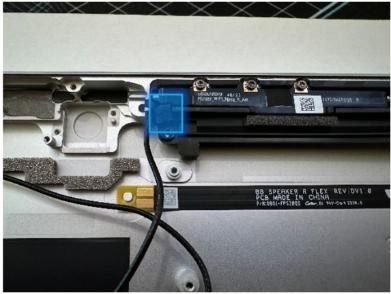
Remove the Antenna Boards and Coax Cables – Using a 3IP (Torx-plus) driver, remove the 6 screws holding in the Antenna Boards. The coax cables are attached to the boards, so don't separate them during removal. Lift out of the Enclosure and set aside for reuse.
Remove the fan duct Bracket – Using a 3IP (Torx-plus) driver, remove the 1 screw securing the Bracket. Once removed, lift the Bracket out of the Enclosure and set aside for reuse.

- Remove the Battery – Remove 9 screws. Lift the battery from the original enclosure and install it directly into the new bucket. Lift the battery from the sides on the frame. Refer to the Procedure – Removal (Battery) section for detailed instructions.
Procedure - Installation (Enclosure)
- Finish installation of the Battery – Install 8 screws around the
frame with
screws and 1 screw in the middle with a
screw. Refer to the Procedure – Installation (Battery) section for detailed
instructions.
- Install the fan duct Bracket – Place the bracket back into place
in the new Enclosure and using a 3IP (Torx-plus) driver, fasten the
1 screw (13NL-5LN0B03 – bag labeled with
and
 ) until finger tight then turn it an more 1/8th turn
(45-degrees) until it's secure.
) until finger tight then turn it an more 1/8th turn
(45-degrees) until it's secure.
Install the Motherboard – Install the motherboard by toeing it in on the left side and fasten 5 screws (
and
).
Reconnect the 2 coax cables, battery connector and 5 camera FPCs at
the top. See the Procedure – Installation (Motherboard) section for
detailed instructions.Install the Antenna Boards with Coax Cables – Place the Antenna Boards and Coax Cables into the Enclosure. Using a 3IP (Torx-plus) driver, secure both boards with 6 screws (bag labeled with
) – 3 screws each. Route the cables as shown and connect them
to the Motherboard using the flat end of a Nylon Spudger. Refer to
the Procedure – Installation (Motherboard) section for
detailed instructions.
Important
Be sure to be careful when connecting the antenna cables as they're sensitive. Each cable should be pressed into the connector on the board until a click is heard.
Install the fan duct foam – Using tweezers to hold the foam, carefully place the foam on top of the cable in the cutout shown.
Install the Rear Camera – Install the rear camera with 2 screws (
) and connect the FPC to the motherboard. Refer to the Procedure – Installation (Rear Camera)
section for detailed instructions.Install the Front Camera – The enclosure comes with the camera PSA preinstalled with a liner on top. With the original camera covered with a cap, use the pin holes to line up the camera and install it on top of the PSA. Press it down for 10 seconds. Connect the FPC to the motherboard. Refer to the Procedure – Installation (Front Camera) section for detailed instructions.
Install the Microphone Module – Remove the front camera cover before starting. Install the mic deck with 4 screws (
) and connect 3 FPCs to the motherboard. Refer to the Procedure – Installation (Microphone Module) section for detailed instructions.Install the Thermal Module + Fan – Apply new thermal pads to the thermal module or motherboard and place thermal module on top. Fasten 14 screws labeled with
,
,
,
on the bags and reconnect the FPC to the motherboard. Apply a new VC
tape to the thermal module. Refer to the Procedure – Installation (Thermal Module + Fan) section
for detailed instructions.Install the Button board – Install the button PCB and secure with 2 screws (
). Assemble the tape and foam (VC gasket - 13NL-5LU0D11) spreading
across the button board and thermal module Refer to the
Procedure – Installation (Buttons) section for detailed
instructions.Install the Speakers – Install both speakers with 3 screws each (
). Refer to the Procedure – Installation (Speakers) section
for detailed instructions.Install the Surface Connect Port Cable – Apply the new Surface Connect PSA on the cable. Insert the cable into the enclosure and connect it to the motherboard. Secure with 2 screws (
). Refer to the
Procedure – Installation (Surface Connect Port) section for
detailed instructions.Install the Display Module – Install 2 new NFC foams. Reconnect the display FPC and install a new shield and shield tape on top. Align new PSA strips and install new speaker meshes on the display. Align the display on the bottom edge and press onto device. Use bonding frame tool to apply weight. Refer to the Procedure – Installation (Display Module) section for detailed instructions.
Install the Removable Solid-State Drive - Turn the device over, reinstall the solid-state drive and fasten a new screw from the bag labeled
. Refer to the Procedure – Installation (Removable Solid-State Drive)
section for detailed instructions.Install the Removable Solid-State Drive Door – Refer to the Procedure – Installation (Solid-State Drive Door) section for detailed instructions.
Power on device – Carefully place device screen side up. Connect the device to a power supply, open display, and power on to the Windows desktop screen.
Run the Surface Diagnostic Toolkit (SDT) - Run SDT’s full diagnostic test to ensure device functions as expected.
Power down device – Power down device using the OS start menu.