Note
Access to this page requires authorization. You can try signing in or changing directories.
Access to this page requires authorization. You can try changing directories.
Warning
Review the General Safety Precautions and Battery Safety guidelines in their entirety before proceeding with any repair steps.
Important
Read this Guide in its entirety before starting any repairs. If at any point you're unsure or uncomfortable about performing the repairs, as detailed in this Guide, DO NOT proceed. Contact Microsoft for more support options.
Warning
Failure to follow the instructions in this Guide, use of non-Microsoft (nongenuine), incompatible, or modified replacement parts, and/or failure to use proper tools could result in serious injury, death, and/or damage to the product or other property.
Prerequisite Steps
Steps outlined in this section should be conducted before starting any repair on a Surface device.
Power off device – Ensure the device is powered off completely and the battery has been fully discharged. Refer to the Repair-specific precautions and warnings section for guidelines. Once discharged, the device should be disconnected from all power sources.
ESD Prevention – Ensure ESD prevention steps and general guidelines are followed before opening the device. Refer to the ESD Prevention section for guidelines.
Position Device – To prevent damage to the device, ensure the device is placed on a clean surface free of debris.
Kickstand Replacement Process
Preliminary Requirements
Important
Be sure to follow all special (bolded) notes of caution within each process section.
Required Tools and Components
Tools:
3IP (Torx-plus) driver
Loctite 649
Loctite 243
Soft ESD safe mat
Microfiber cloth
Components:
- Kickstand (Refer to Illustrated Service Parts List)
- Kickstand Screws (M1183405) Qty. 2
Prerequisite Steps
- Power off device – Ensure device is powered off and disconnected from a power supply.
- General Safety – Check to make sure that general guidelines and ESD compliance steps are followed before opening device. Refer to Prior to Device Disassembly section for details.
Procedure - Removal (Kickstand)
Place device screen-down on soft ESD-safe mat – Ensure mat is clear of any abrasive material that might scratch the Touch Display Module (display) glass.
Extend the kickstand to approximately 90-degrees.

Remove hinge screws – Use your finger to hold the back of the kickstand behind the hinge while removing the hinge screws. One screw for each hinge. Ensure screws don't fall into the hinge opening.

Angle Kickstand Down – Firmly grip the hinges and the kickstand between thumb and index fingers. Rotate the kickstand from 90 degrees to approximately 45 degrees.

Release Kickstand Threaded Bosses – Using fingers on the underside of the kickstand and thumb on the topside, slightly rotate the kickstand about the axis as shown. The kickstand should rotate ~5 degrees to free the two threaded bosses of the kickstand from the recesses of the hinges.

Remove Kickstand – Using the palm of your hand, firmly hold the device down from the center of the chassis. Simultaneously, grip the kickstand off-center between your thumb and index finger and firmly pull. Pull with a moderate amount of force until the foam inserts slide out of the device. If the kickstand is stuck, ensure the threaded bosses haven't slipped back into the recess on the hinges.

Warning
Inspect Removed Kickstand Foam Tabs – Damaged foam or tabs can't be safely removed. Attempts to do so can damage internal components. Don't insert anything other than the tabs into the slots. Ensure both tabs are complete and show no signs of tearing. Don't attempt to remove it from the interior of the device, instead proceed to Procedure – Removal (Chassis) to replace the old chassis.
Procedure - Installation (Kickstand)
Important
Use caution when handling new kickstand assembly to avoid cosmetic damage of the kickstand and the device.
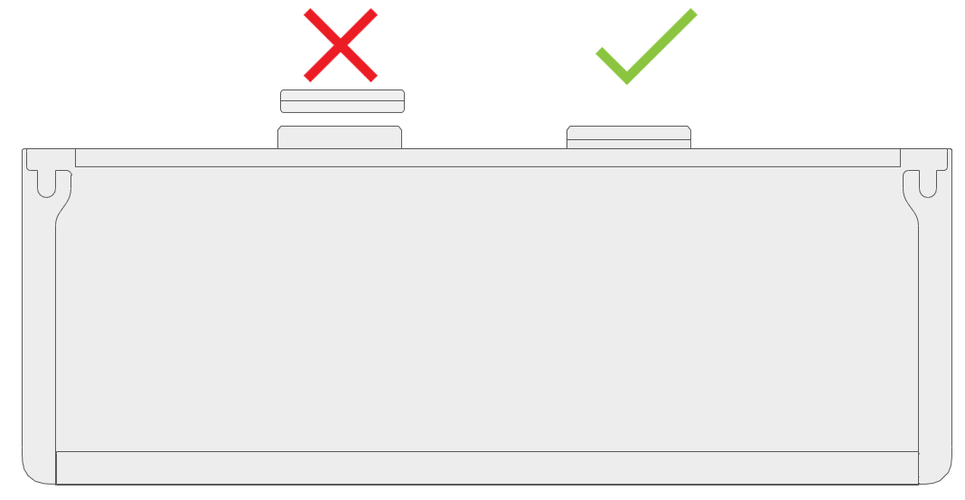
- Insert Foam Tabs – With the hinges still at ~ 45-degrees start to slide the new kickstand’s foam tabs into the slots on the back of the chassis. Foam should slide in with minimal force – don't crumple the foam by using excess force. Don't slide the foam completely into the device – insert the foam tabs until ~3/4 of the foam tabs are inside the device.
Caution
Don't use any tool or sharp object to assist inserting the tabs into the slots. Only the tabs should be inserted. Doing so could damage internal components.

Slot Outer Lip of Hinge into Kickstand – Using fingers on the underside of the kickstand and thumb on the topside, slightly rotate the kickstand about the axis as shown. The kickstand should rotate ~5-degrees to catch the outer lip of the hinge. Push the kickstand toward the device.

Slip Kickstand Threaded Bosses into Hinge Recesses – Maintaining pressure on the kickstand to prevent it from backing out, rotate the kickstand down into place (Figure 7-9). The threaded bosses of the kickstand should slip into the recesses of the hinges.

Rotate the Kickstand Up – Firmly grip the hinges and the kickstand between thumb and index fingers as shown. Rotate the kickstand from 45-degrees to approximately 90-degrees.
Apply thread locker to screws – Brush new screws with Loctite 649 Activator. Let screws sit for 2 minutes after activator is applied before assembling to device.

Apply thread locker to screws bosses – Apply one drop of Loctite 243 thread locker to each screw boss.

Install hinge screws – Use your finger to hold the back of the kickstand behind the hinge while installing the screws until they're fully seated. Ensure the kickstand is properly aligned and seated in the hinges, then tighten the screws another ~quarter turn (~ 90-degrees). Be careful to tighten the screws only until snug and not to strip the kickstand threads. Ensure screws don't fall into hinge opening.

Final inspection Kickstand installation – Fold down the kickstand and peel off protective plastic from the kickstand and logo if present. Verify the side edges of the kickstand are aligned with the midframe walls and that there are no obvious steps/gaps between the kickstand and the chassis. Wipe the device thoroughly (including under the kickstand) with the microfiber cloth to remove all fingerprints.
rSSD Door Replacement Process
Preliminary Requirements
Required Tools and Components
Tools:
- SIM ejector tool (or equivalent 0.58 mm / 0.023-in. diameter paperclip)
- Soft ESD safe mat
- Microfiber cloth
Components:
- rSSD Door (Refer to Illustrated Service Parts List)
Prerequisite Steps
- Power off device – Ensure device is powered off and disconnected from a power supply.
- General Safety – Check to make sure that general guidelines and ESD compliance steps are followed before opening device. Refer to Prior to Device Disassembly section for details.
Procedure - Removal (rSSD Door)
Place device screen-down on soft ESD-safe mat – Ensure mat is clear of any abrasive material that might scratch the Touch Display Module (display) glass.
Extend the kickstand to approximately 90-degrees.

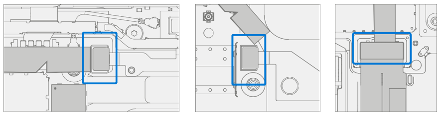
Remove rSSD door – Using a SIM eject tool (or equivalent paperclip) press down into slot on door till it pops open and lift out.

Procedure - Installation (rSSD Door)
Install rSSD door – Slot in replacement door and press down.

rSSD Replacement Process
Preliminary Requirements
Important
Be sure to follow all special (bolded) notes of caution within each process section.
Required Tools and Components
Tools:
- SIM ejector tool (or equivalent 0.58 mm / 0.023-in. diameter paperclip)
- 3IP (Torx-plus) driver
- Anti-static wrist strap (1 MOhm resistance)
- Soft ESD safe mat
- Microfiber / Lint free cloth
Components:
- rSSD (Refer to Illustrated Service Parts List)
- rSSD Screw (M1186577-001) Qty. 1
Prerequisite Steps
- Power off device – Ensure device is powered off and disconnected from a power supply.
- General Safety – Check to make sure that general guidelines and ESD compliance steps are followed before opening device. Refer to Prior to Device Disassembly section for details
Procedure - Removal (rSSD)
Place device screen-down on soft ESD-safe mat – Ensure mat is clear of any abrasive material that might scratch the Touch Display Module (display) glass.
Extend the kickstand to approximately 90-degrees.

Remove rSSD door – Using a SIM eject tool (or equivalent paperclip) press down into slot on door till it pops open and lift out.

Remove rSSD screw – Use a 3IP (Torx-plus) driver to remove the screw securing the rSSD.
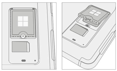
Remove rSSD – The rSSD should lift upwards to ~15-degree tilt after screw is removed. Carefully grab sides of rSSD case and pull out of main board socket at same ~15-degree angle.

Procedure - Installation (rSSD)
Important
Only a rSSD of like capacity should be replaced in the device.
Insert rSSD – Insert the connector end of the rSSD into the rSSD connector on Main board at ~ 15-degree angle.

Install new rSSD screw – Use a 3IP (Torx-plus) driver to install a new rSSD screw until the screw is snug and seated, and then turn another 45 degrees (1/8 turn) or until screw is fully fastened.

Install rSSD door – Slot in door and press down.

Imaging – Image the new rSSD by using a BMR Imaging USB drive specific to the device model.
Important
Refer to Surface imaging process - Surface Imaging Tools
- Run SDT – Power on device and connect USB drive with SDT Configuration Files. Run SDT to ensure all device features and functions operate as expected.
rSSD Swap to a New Device Process
Preliminary Requirements
Important
Be sure to follow all special (bolded) notes, cautions, & warnings in each process section. The rSSD 3IP screw is reused in this process. Only a Microsoft rSSD of like capacity should be replaced in the device.
Required Tools and Components
Tools:
- SIM ejector tool (or equivalent 0.58 mm / 0.023-in. diameter paperclip)
- 3IP (Torx-plus) driver
- Anti-static wrist strap (1 MOhm resistance)
- Soft ESD safe mat
- Microfiber / Lint free cloth
- USB Drive
- Surface Dock
- Wired Ethernet connection to the Internet
- USB keyboard
Components:
- New rSSD Door if necessary. (Refer to Illustrated Service Parts List)
Prerequisite Steps
Using an Internet connection install all available updates: Navigate to Settings -> Update and Security* and check for Windows Update.
Consumer using Windows Home:
- The BitLocker recovery key is automatically generated for users with an MSA and can be found by the user by searching the web for “BitLocker recovery key” and logging into their MSA. If the user doesn't have an MSA based account, the disk won't be encrypted.
Commercial using Windows Pro:
- This is managed via commercial policy, and each business might have their own BitLocker policy / recovery method.
- Confirm that the customer knows the Windows password to the device.
General Safety – Check to make sure that general guidelines and ESD compliance steps are followed before opening device. Refer to Prior to Device Disassembly section for details.
Procedure - Swap (rSSD)
Manage BitLocker
- If rSSD remains encrypted during swap
- Navigate to Bitlocker -> Manage Bitlocker -> Generate Bitlocker Recovery Key.
- Plug in USB drive.
- Save the recovery key to USB storage.
- Remove the USB drive.
- If rSSD can be unencrypted before swap
- Navigate to Bitlocker -> Manage Bitlocker.
- Select Turn Off Bitlocker.
- If rSSD remains encrypted during swap
Place device screen-down on soft ESD-safe mat – Ensure mat is clear of any abrasive material that might scratch the Touch Display Module (display) glass.
Extend the kickstand to approximately 90-degrees.

Remove rSSD door – Using a SIM eject tool (or equivalent paperclip) press down into slot on door till it pops open and lift out.

Remove SIM – If present in customer’s old device, push edge of SIM card to release from device.

Remove rSSD screw – Use a 3IP (Torx-plus) driver to remove the screw securing the rSSD.

Remove rSSD – The rSSD should lift upwards to ~15-degree tilt after screw is removed. Carefully grab sides of rSSD case and pull out of main board socket at same ~15-degree angle.

rSSD Swap – Insert rSSD removed from the new device into customer’s original device, then insert customer’s original rSSD into new device. Insert the connector end of the rSSD into the rSSD connector on Main board at ~15-degree angle.

Install new rSSD screw – Use a 3IP (Torx-plus) driver to install a new rSSD screw until the screw is snug and seated, and then turn another 45 degrees (1/8 turn) or until screw is fully fastened.

Install SIM – If present from the customer’s old device, install SIM card in the new device.

Install rSSD door – Slot in door and press down.

Plug new device into power and wired Internet connection.
Power on new device – The device might go through a firmware update during startup.
If the SSD remained encrypted during the swap:
- Plug in USB drive with BitLocker recovery key.
- Open the .txt file with the BitLocker recovery key.
- Manually enter the recovery key into the new device.
Connect a keyboard to the new device.
Navigate to Sign-In Options -> Password (key icon on the left side).
Customer enters Windows password. Select “Sign In”.
Customer might need to go through two-factor authentication.
Once fully signed in, navigate to Start -> Account -> Sign Out.
Customer signs in with Windows password again.
Customer prompted to setup Windows Hello and PIN.
- If the device was previously Bit locked, navigate to Bitlocker ->Manage Bitlocker -> Resume Bitlocker.
Run SDT – Power on device and connect USB drive with SDT Configuration Files. Run SDT to ensure all device features and functions operate as expected.
Check Windows activation – Navigate to Settings -> Activation. If there's any error message, select Troubleshoot.
Check Office Account – Open Office app and then navigate to File > Account and check for any error messages.
Check cellular – If SIM card is present, unplug device from wired network and disable WiFi. Check that cellular network shows connected, and that the device can open a webpage.
Display Replacement Process
Preliminary Requirements
Important
Be sure to follow all special (bolded) notes, cautions, & warnings in each process section.
Required Tools and Components
Tools:
- 3IP (Torx-plus) driver
- Anti-static wrist strap (1 MOhm resistance)
- Soft ESD safe mat
- Microfiber / lint free cloth
- Isopropyl alcohol dispenser bottle (use 91% or greater IPA)
- Cotton swab
- USB drive with Surface Diagnostic Toolkit
- Spudger
- Plastic opening pick
- Two 2 in spring clamps
- Add display
- Add dongle
- Surface Display Debonding Tool
- Surface Display Bonding Frame
- Foam Pad (comes with Display bonding frame, recommended McMaster PN: 86095K43)
- Display bonding weights 32 kg (Recommended using three Ruck weights two 9 kg, one 14 kg) (Alternate using steel shot bags two 9 kg, one 14 kg)
Components:
- Display (Refer to Illustrated Service Parts List)
Prerequisite Steps
- Prep Device – Device must be set in Display Replacement Mode before removing a faulty display.
Connect software tools USB drive – Use SDT to USB connector on device under repair.
Connect power supply to device.
Power on device – Depress the power button on the side of the device.
Run software tool – At the device OS, use Windows Explorer, navigate to USB drive and run:
SDT – Select Repair setup and validation. Run the Touch Display Setup. At the end of the tool process device powers down.
Important
The device must first be set in Display Replacement Mode before broken/defective display is removed from the device. Software tools are provided for this purpose. Device must be functional to the point that software tools can be run on device from within the Windows OS. If display on device is nonfunctional, there's no display, or it's unreadable, connect an external PC monitor and keyboard to the device’s USB C port or Surflink port. If this can't be completed, then the device isn't a good candidate for repair.
Important
This step must be conducted on the device successfully before removal of a faulty display. Ensure light levels in the work area remain consistent during the touch display setup process.
Warning
Don't use a heat gun or hair dryer to debond display
- Power off device – Ensure device is powered off and disconnected from a power supply. Remove all attached cables and drives.
- General Safety – Check to make sure that general guidelines and ESD compliance steps are followed before opening device. Refer to Prior to Device Disassembly section for details.
- Remove rSSD – Remove the rSSD as detailed in the Procedure – Removal (rSSD).
Procedure - Removal (Display)
Speaker mesh preparation – Place the device face up on a Soft ESD safe mat. Use an iFixit opening tool to widen the gap between the right speaker mesh and device. Push the sharp edge into the gap and side to side along the device edge. Once the flat tip fits fully in the gap, use it to push the speaker mesh towards the device, repeating uniformly along the length of the speaker mesh. The metal mesh will either fold lengthwise or slide completely under the glass. Repeat this process for left speaker mesh.

Mark Display Debonding Tool pick depth – To prevent damage to internal components use a metric ruler to draw a 2-mm mark and 8-mm mark on the plastic pick.

Display Debonding Tool
- Install marked pick in the holder with the marks in view. Use a 3 mm Allen Driver to adjust pick height to the lowest setting.

- Clamp debonding tool to edge of workbench. Ensure the cut depth adjustment can be accessed while the tool is clamped down.

- Place the right-side speaker edge of the device in the debonding tool above the pick. Adjust the pick height to the 2-mm mark. Ensure it enters the gap between the display and bucket edge.

- With both hands, draw the right side of the device through the debonding tool track.

- At the bottom right corner rotate the device in the debonding tool track. Draw the bottom side of the device through the debonding tool track.

- At the bottom left corner rotate the device in the debonding tool track. Draw the left side of the device through the debonding tool track.

- At the top left corner rotate the device in the debonding tool track. Draw the top side of the device through the debonding tool track.

- Place the top left edge of the device in the debonding tool track. Adjust the pick height to the 8-mm mark. Ensure it enters the gap between the display and bucket edge. With both hands, draw the top edge of the device through the debonding tool track.

Caution
Don't insert the pick more than 2 mm along the left and right sides or bottom edge of the display. The pick depth shouldn't exceed 8 mm along the top edge of the display.

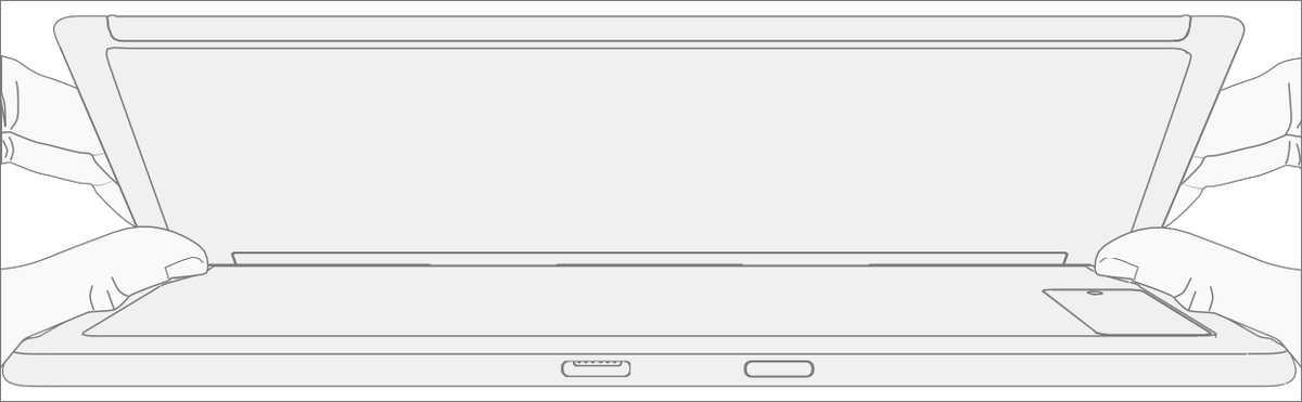
- Separate display from chassis – Gently pull up vertically on the top edge of the glass while pushing down on the chassis to separate the glass. Lift the edges of the display and inspect for any remaining adhesive. Slice or remove (with an iFixit Pick) any strands still connecting the display to the chassis.
Warning
It's recommended that a Microsoft provided ESD-safe battery cover appropriate for size is placed across the device to protect the battery from any accidental damage during repair. Ensure corners of cover are always aligned with the corners of the device during repair. If battery cover is misaligned during the repair operation in any way, realign before continuing repair activities.

- Disconnect display connector – Lay the display down gently next to the chassis on the work surface. Remove the shield lid on the display connector by inserting pointed end of a spudger or tweezers underneath the inner edge of the shield. Then gently pull upwards and the shield will come off. Disconnect the display connector using the pointed end of a spudger.
Warning
Don't pull on the Display FPC to disconnect the display.

Remove speaker mesh from chassis – Remove any remaining speaker mesh from the chassis. Use a handheld pick to remove it by inserting the pick between the Speaker mesh and the enclosure. Confirm a successful removal of the speaker mesh and its adhesive by verifying the three cutouts of the chassis are exposed, as shown.
Remove residual adhesive – Using IPA and cotton swabs clean residual PSA off the chassis. Ensure area around the Camera and IR Sensor is clean and free of any dust or other contamination. Wipe the area around the camera with a lint free cloth.
Procedure - Installation (Display)
- Pre-installation Device Inspection
Warning
Verify the battery’s condition. Devices exhibiting battery issues as outlined in the Battery Inspection Process require whole unit replacement.
Important
Leave protective cling on new display during all installation steps.
Important
Carefully inspect the internal areas of the bucket. Ensure the area around battery is free of any foreign objects.
Display adhesive application – Thoroughly clean the chassis along the display PSA bonding surface using IPA and a cotton swab. Wait at least 30 seconds before applying the new PSA. Apply the 4 strips of PSA to the chassis. Align the PSA following the outline on the chassis. Leave the blue liner on the PSA, it's removed at a later step. Refer to the illustration for PSA locations.

Speaker mesh application – Place the display face-down on a Soft ESD safe mat. Wipe down the outer edges of the display with a lint free cloth. When installing the originally removed display ensure outer edges are clean and clear of PSA residue. Remove the protective liner from the speaker mesh. Using the clear handle, align the speaker mesh into the chassis speaker opening. Press onto the mesh for 10 seconds to activate the adhesive. Carefully remove the clear handle. Repeat this process for the other side of the chassis.

Final Inspection – Prior to continuing with the reassembly, inspect the device internals to ensure no screws, foam, tape, or other foreign material has been misplaced. If any damage is observed to the battery, contact Microsoft for a device exchange.
Connect display connector – While supporting the display with one hand, connect the Display FPC by pressing it into the mating connector on the display. Install a new shield over the Display FPC. Ensure all edges of the shield are snapped into place.

Apply display to chassis – Hold the display and remove the PSA Liners to expose adhesive. Turn the display over and place it on the chassis. Align the display along the top edge first (Toe-in) and lower after alignment is found. Ensure that the glass sits flush in the chassis and doesn't rest anywhere on top of the chassis lip.

Bond adhesive – Place the bonding frame on the device, ensuring that the cutouts on the sides line up with the volume/power buttons. Place foam pad over bonding frame. Place 32 kg of weight on top of the foam pad and bonding fame. Leave weight in place for 2 minutes.
Important
Weight Requirement: Minimum 32 kg (70 lbs.) / Maximum 35 kg (77 lbs.) Minimum Dimensions: 280mm x 200mm
Geometry must be symmetrical, to allow for even weight distribution. Weight used must be a flat plate, with consistent flatness and not protrude from contact plane with Bonding Frame.
Weight must contact the full perimeter of the frame when placed above it. Recommended weights (Ruck Plates of 9 kg + 9 kg + 14 kg, or 20 lbs. + 20 lbs. + 30 lbs.)
When using Ruck weights place the 14-kg weight first, then stack the 9-kg weights on top. Ensure foam pad covers entire bonding frame.

After bonding inspection – Remove the weights, foam pad, and the frame. Lift carefully to avoid damaging the device. Inspect the display for scratches, cracks, large gaps, and its flushness with respect to the chassis.
Install rSSD – Install the rSSD as detailed in the Procedure – Installation (rSSD).
New display calibration – On installation of a new display device final calibration relies on the successful completion of the display Replacement Mode. Display calibration isn't required when installing the originally removed display.
Connect software tools USB drive with SDT to USB connector on device under repair.
Power on device – Depress the power button on the side of the device.
Run software tool – At the device OS, use Windows Explorer, navigate to USB drive, and run:
SDT – Select Repair setup and validation. Run the Touch Display Calibration. Accept the restart prompt at the end of the tool process.
Important
This step must be conducted on the device successfully on installation of a new display. Ensure light levels in the work area remain consistent during the touch display calibration process. Any tool failures require restarting the process with a new display.
- Run SDT – Power on device and connect USB drive with SDT Configuration Files. Run SDT to ensure all device features and functions operate as expected.
- Final inspection of display installation – Remove protective cling from the new display. Verify the side edges of the display are flush, and that there are no obvious steps/gaps between the display and the chassis. Wipe the device thoroughly (including under the kickstand) with the microfiber cloth to remove all fingerprints.
Procedure - Alternate Installation (Display)
- Pre-installation Device Inspection
Warning
Verify the battery’s condition. Devices exhibiting battery issues as outlined in the Battery Inspection Process require whole unit replacement.
Important
Leave protective cling on new Display during all installation steps.
Important
Carefully inspect the internal areas of the bucket. Ensure the area around battery is free of any foreign objects.
Display adhesive application – Thoroughly clean the chassis along the display PSA bonding surface using IPA and a cotton swab. Wait at least 30 seconds before applying the new PSA. Apply the 4 strips of PSA to the chassis. Align the PSA following the outline on the chassis. Leave the blue liner on the PSA, it's removed at a later step. Refer to the illustration for PSA locations.

Speaker mesh application – Place the display face-down on a Soft ESD safe mat. Wipe down the outer edges of the display with a lint free cloth. When installing the originally removed display ensure outer edges are clean and clear of PSA residue. Remove the protective liner from the speaker mesh. Using the clear handle, align the speaker mesh into the chassis speaker opening. Press onto the mesh for 10 seconds to activate the adhesive. Carefully remove the clear handle. Repeat this process for the other side of the chassis.

Connect Display FPC – While supporting the display with one hand, connect the Display FPC by pressing it into the mating connector on the reverse side of the display. Install a new shield over the Display FPC. Ensure all edges of the shield are snapped into place.

Apply display to chassis – Hold the display and remove the PSA Liners to expose adhesive. Turn the display over and place it on the chassis. Align the display along the top edge first (Toe-in) and lower after alignment is found. Ensure that the glass sits flush in the chassis and doesn't rest anywhere on top of the chassis lip. Lightly press on the edges of the display to create an initial bond.

Alternate bonding PSA – Bonding is a multi-step process. Refer to the illustrations.
Important
Use steel shot bags, two 9 kg, and one 14 kg. Apply the 1st 9-kg bag, then the 14-kg bag, and then the 2nd 9-kg bag.
Top of device (Camera Region)


After bonding inspection – Remove the steel shot bags and lift device out of the frame. Lift carefully to avoid damaging the device. Inspect the display for scratches, cracks, large gaps, and its flushness with respect to the chassis.
Install rSSD – Install the rSSD as detailed in the Procedure – Installation (rSSD).
New display calibration – On installation of a new display device final calibration relies on the successful completion of the Display Replacement Mode. Display calibration isn't required when installing the originally removed display.
Connect software tools USB drive with SDT to USB connector on device under repair.
Power on device – Depress the power button on the side of the device.
Run software tool – At the device OS, use Windows Explorer, navigate to USB drive, and run:
SDT – Select Repair setup and validation. Run the Touch Display Calibration. Accept the restart prompt at the end of the tool process.
Important
This step must be conducted on the device successfully on installation of a new display. Ensure light levels in the work area remain consistent during the touch display calibration process. Any tool failures require restarting the process with a new display.
Run SDT – Run SDT to ensure all device features and functions operate as expected.
Final inspection display installation – Remove protective cling from the display. Verify the side edges of the display are flush, and that there are no obvious steps/gaps between the display and the chassis. Wipe the device thoroughly (including under the kickstand) with the microfiber cloth to remove all fingerprints.
Surflink Replacement Process
Preliminary Requirements
Important
Be sure to follow all special (bolded) notes, cautions, & warnings in each process section.
Required Tools and Components
Tools:
- 3IP (Torx-plus) driver
- Anti-static wrist strap (1 MOhm resistance)
- Soft ESD safe mat
- Microfiber / lint free cloth
- Isopropyl alcohol dispenser bottle (use 91% or greater IPA)
- Cotton swab
- USB drive with Surface Diagnostic Toolkit
- Spudger
Components:
- Surflink (Refer to Illustrated Service Parts List)
- Surflink Screws (M1164319-001) Qty. 2
Prerequisite Steps
- Power off device – Ensure device is powered off and disconnected from a power supply.
- General Safety – Check to make sure that general guidelines and ESD compliance steps are followed before opening device. Refer to Prior to Device Disassembly section for details.
- Remove rSSD – Remove the rSSD as detailed in the Procedure – Removal (rSSD).
- Remove Display – Remove the display as detailed in the Procedure – Removal (Display).
Procedure - Removal (Surflink)
Remove T2 shield – Carefully remove the T2 shield lid to expose the board-to-board connector of the display FPC. Disconnect and remove the display FPC from the device.

Disconnect cable from motherboard – Before disengaging connector, remove tape using a spudger. Use a spudger to release locking bar and disconnect Surflink connector from motherboard. Use a plastic spudger to disengage the cable from the connector. Gently peel the Surflink cable up to release it from the unit.
Important
When removing the cable, note there's light adhesive under the cable. Once removed, clean the surface with an IPA wipe.
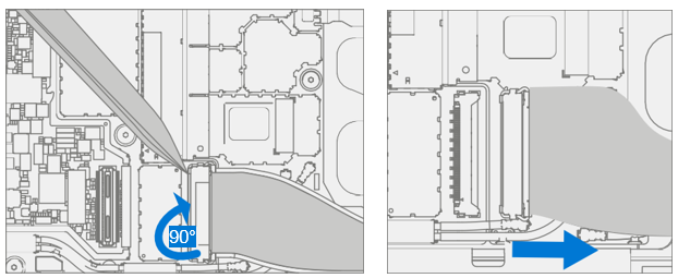
- Screw removal – Use a 3IP (Torx-plus) driver to remove the Surflink screws.
Caution
The Surflink cable is magnetized. Be careful to not let the screws stick to it during screw removal.
- Surflink removal – Gently peel up the Surflink from the chassis. Take extra care not to damage the fan under the Surflink.
Procedure - Installation (Surflink)
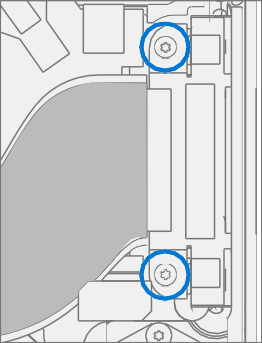
- Install screws – Install new Surflink into chassis. Ensure alignment by confirming the through holes on the connector are aligned with the corresponding screw bosses in the chassis. Use a 3IP (Torx-plus) driver to install the Surflink screws until they're snug and seated, and then turn another 45 degrees (1/8 turn) or until screws are fully fastened. Refer to the illustration for screw locations.
Caution
The Surflink cable is magnetized. Be careful to not let the screws stick to it during screw installation.
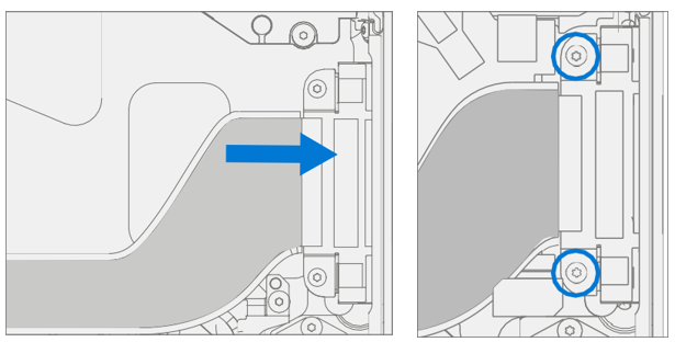
Connect cable to motherboard – Connect Surflink cable to the motherboard. Press down on the locking buckle to secure the connector. Apply tape over the retention latch after connecting and securing cable.

Reassemble display FPC – Connect the display FPC to the motherboard. Use the printed text to identify the side that will connect to the motherboard.

Install new display FPC Shield – Use a new display FPC shield lid and install it over the motherboard shield fence. Press down along the perimeter to ensure it's secured in place.

Install Display – Install the display as detailed in the Procedure – Installation (Display)..
Install rSSD – Install the rSSD as detailed in the Procedure – Installation (rSSD).
Run SDT – Power on device and connect USB drive with SDT Configuration Files. Run SDT to ensure all device features and functions operate as expected.
Thermal Module Replacement Process
Preliminary Requirements
Important
Be sure to follow all special (bolded) notes, cautions, & warnings in each process section.
Required Tools and Components
Tools:
- 3IP (Torx-plus) driver
- Anti-static wrist strap (1 MOhm resistance)
- Soft ESD safe mat
- Microfiber / lint free cloth
- Isopropyl alcohol dispenser bottle (use 91% or greater IPA)
- Cotton swabs
- USB drive with Surface Diagnostic Toolkit
- Spudger
- Plastic tweezers
Components:
- Thermal Module (Refer to Illustrated Service Parts List)
- SOC Screws (M1196939-001) Qty. 4
- Heat Spreader Screws (M1182860) Qty. 2
- Center Screws (MM1182877-001) Qty. 2
- Thermal Putty (M1019757-006) Qty. 1
Prerequisite Steps
- Power off device – Ensure device is powered off and disconnected from a power supply.
- General Safety – Check to make sure that general guidelines and ESD compliance steps are followed before opening device. Refer to Prior to Device Disassembly section for details.
- Remove rSSD – Remove the rSSD as detailed in the Procedure – Removal (rSSD).
- Remove Display – Remove the display as detailed in the Procedure – Removal (Display).
- Remove Surflink – Remove the display as detailed in the Procedure – Removal (Surflink).
Procedure - Removal (Thermal Module)
Remove T1 Shield Lid – Insert a pair of plastic tweezers or spudger near the bottom right corner of the shield to lift the lid and remove.

Screw removal – Use a 3IP (Torx-plus) driver to remove the 8 screws securing the thermal module to the motherboard.
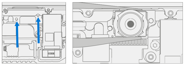
Release the TIM from the motherboard and remove – Using a plastic spudger apply light pressure to the edges of the THM copper shield on the motherboard as pictured. Carefully lift thermal module from the chassis. Note that shield spring gasket might also come off with the thermal module.
Caution
Place spudger between the heat pipe and shield to not cause damage to the motherboard.

Clean TIM from processor – Using a plastic spudger, scrape TIM from SoC area. Use IPA and cotton swab to clean residual TIM from SoC.

Procedure - Installation (Thermal Module)
Warning
Don't reuse the old thermal module when carrying out any repairs. A new thermal module must be used for each repair.
Spring gasket placement – If the original gasket appears damaged replace it with a new spring gasket. Ensure the spring gasket is correctly placed over the motherboard, then center and align the thermal module to the spring gasket.

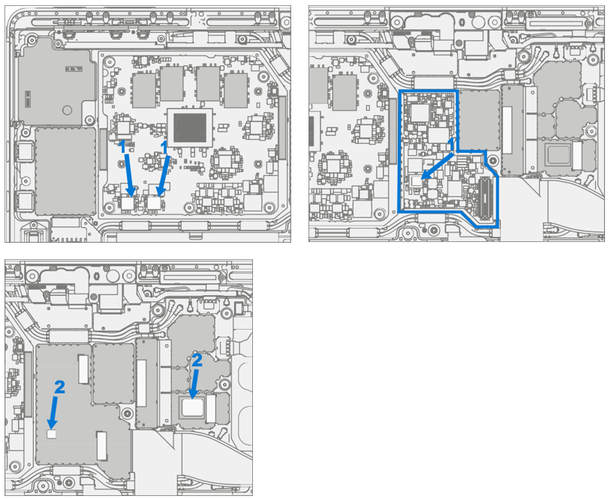
Apply thermal putty – Using the provided syringe, dispense the equivalent of one tick marking of the syringe onto the locations marked 1. Install shield over blue highlighted area. Dispense the equivalent of two tick markings on the syringe to the locations marked 2.
Align thermal module with chassis – Locate the right heat pipe onto the corresponding alignment pin on the bucket. The left alignment feature can also be found on the bucket and must be aligned with the alignment slot on the left heat pipe.

Install thermal module – Use a 3IP (Torx-plus) driver to install the 8 screws until snug and seated, and then turn another 45 degrees (1/8 turn) or until fully fastened. Refer to the illustration for screw locations and part numbers.
Warning
The thermal module is fragile. Take extra care to not bend or twist the thermal module. If any part of the thermal module or its heat pipes are bent, then the whole module must be replaced.

Install Surflink – Install the Surflink as detailed in the Procedure – Installation (Surflink).
Install Display – Install the display as detailed in the Procedure – Installation (Display).
Install rSSD – Install the rSSD as detailed in the Procedure – Installation (rSSD).
Run SDT – Run SDT to ensure all device features and functions operate as expected.
Battery Replacement Process
Preliminary Requirements Required Tools and Components
Tools:
- 3IP (Torx-plus) driver
- Anti-static wrist strap (1 MOhm resistance)
- Soft ESD safe mat
- Microfiber / lint free cloth
- Gloves
- Safety Glasses
- Bucket of Sand (1 gallon)
- Clean, dry, untreated sand (0.5 gallons)
- Isopropyl alcohol dispenser bottle (use 91% or greater IPA)
- Cotton swab
- USB drive with Surface Diagnostic Toolkit
- Spudger
- Plastic tweezers
Components:
- Battery (Refer to Illustrated Service Parts List)
- Frame Screws (M118260-001) Qty. 7
- Center PCM Screws (M1182861-002) Qty. 2
Prerequisite Steps
- Run SDT – Insert the SDT USB drive and execute the Battery Repair (Setup) workflow to have the device enter repair mode.
- Power off device – Ensure device is powered off and disconnected from a power supply.
- General Safety – Check to make sure that general guidelines and ESD compliance steps are followed before opening device. Refer to Prior to Device Disassembly section for details.
- Remove rSSD – Remove the rSSD as detailed in the Procedure – Removal (rSSD).
- Remove Display – Remove the display as detailed in the Procedure – Removal (Display).
- Remove Surflink – Remove the display as detailed in the Procedure – Removal (Surflink).
- Remove Thermal Module – Remove the thermal module as detailed in the Procedure – Removal (Thermal Module).
Procedure - Removal (Battery)
Warning
It's highly recommended that before handling battery the operator should remove any personal jewelry, wear gloves and safety glasses, and have a bucket of sand prepared in case of any battery event.
Warning
In case of battery event submerge entire device sand in. Don't attempt to pick up device.
Disconnect battery connector – Using a plastic spudger, disconnect the battery connector from the motherboard.

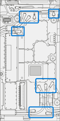
Remove Coax Cable shield – Carefully remove the shield lid covering the bottom coax cables with a pair of tweezers. Then using a plastic spudger, carefully lift the right two from the motherboard.

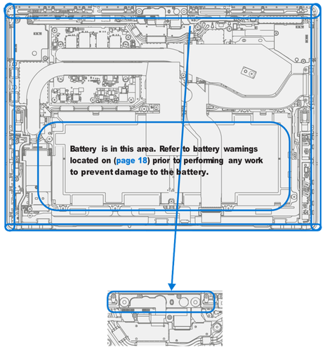
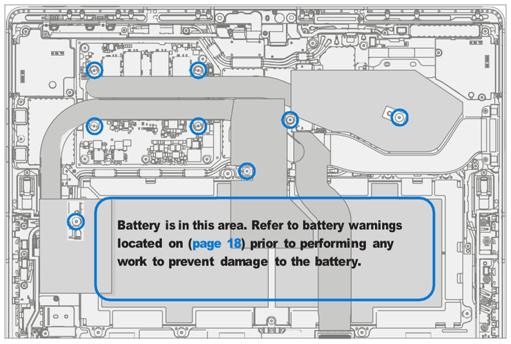
Remove Battery Screws – Use a 3IP driver to remove the 7 screws from the Battery Frame, and 2 center PCM screws as highlighted in red. For the top right screws, use a plastic spudger to move 3 coax cables to expose the screws and avoid damaging the cables during removal.

Lift out the battery – Using two gloved hands, grasp the battery by the frame on both sides as shown and gently lift the battery out of the chassis. Set battery on a clean, flat surface.
Warning
Only handle battery by plastic frame. Bending, twisting, or impacting battery might damage the battery, damage the device, and/or result in severe personal injury or property damage. Always use two hands when handling the battery.
Important
Place the battery in a location where it can't be accidentally contacted or damaged. When replacing the battery dispose of the old battery according to local laws.

Procedure - Installation (Battery)
Important
Don't reuse the old battery when performing repairs. Always use a new battery when the old battery has been removed from the device.
- Pre-installation device inspection – Check the chassis for any loose
articles that might be present.
- Check and remove any foreign object that the magnets might have attracted.
- Pay special attention to the magnetized areas around the bucket edge.
- Verify all removed screws are accounted for and haven't been misplaced inside the device
- Loose screws should never be stored on the magnetic areas of the bucket.
Warning
Verify the battery’s condition. Devices exhibiting battery issues as outlined in the Battery Inspection Process require whole unit replacement.
- Opening the battery packaging – Open the Battery Box and remove the foil pouch. Using both hands, peel open the foil pouch by pulling on the dotted line along the right side, as shown. Remove the contents from the pouch.
Warning
Don't use scissors or other sharp objects to open the pouch.

- Remove the Foam Lid – Remove the foam lid to reveal the replacement battery
Warning
Only handle the new battery with the plastic loops that come attached to the new battery. Bending, twisting, or impacting battery might damage the battery, damage the device, and/or result in severe personal injury or property damage. Always use two hands when handling the battery.
Warning
Don't remove or peel the battery handling liner until the battery has been assembled in the device.

- Insert new battery – Check area under battery for any loose screws/debris before installing new battery into the chassis. Using the attached loops carefully install the new battery into the device.
Caution
If battery is dented or punctured during installation, discard the battery and use a new battery pack.

- Install Battery Screws – Use a 3IP (Torx-plus) driver to install the 7 screws around the battery frame, and 2 center PCM screws as highlighted. For the top right screws, use a plastic spudger to move 3 coax cables to expose the screw holes and avoid damaging the cables during installation. Turn screws until finger tight then tighten by another 1/8 turn (45-degrees) or until fully fastened.
Caution
Don't overtighten screws on battery or battery frame. If frame is cracked battery must not be used.
Caution
Exercise caution when fastening to ensure cables aren't pinched during the operation.

Remove liner – After all screws have been seated, hold one of the tabs on the right or left of the Battery liner to peel the Handling Liner away from the Battery Pack. While working on other components, apply the Battery protective cover to ensure the Battery Pack is protected during the rest of the reassembly steps.
Install coax cable and shield – Carefully align and install the right two coax cables back onto the motherboard ensuring that the stripped portion of the wire makes good contact with the metallic foam. Place the shield lid covering the bottom coax cables with a pair of tweezers and press down to snap into place.

Connect battery connector – Connect battery connector to motherboard by aligning the connector and gently pressing it down with your finger. There should be a small audible snap as you press down lightly.
Warning
Don't apply too much pressure to the connector. Too much pressure can damage the motherboard or the battery connector.

Install Thermal Module – Install the thermal module as detailed in the Procedure – Installation (Thermal Module)
Install Surflink – Install the Surflink as detailed in the Procedure – Installation (Surflink).
Install Display – Install the display as detailed in the Procedure – Installation (Display).
Install rSSD – Install the rSSD as detailed in the Procedure – Installation (rSSD).
New Battery Charging – New batteries are shipped and stored at low states of charge in compliance with shipping regulations. They should be charged up to at least 50%. This step takes between 20 minutes and 1 hour and is needed to validate full functionality of the new battery. Carefully place the device right-side up. Open device, connect the power supply, and power it on.
New Battery Authentication – After charging the new battery to at least 50%, ensure new battery reads as authenticated in the Battery Repair (Validation) workflow in SDT. If the battery shows inauthentic run the SDT Battery Repair (Validation) workflow in its entirety.
- Connect the SDT Configuration USB drive.
- Run the SDT Battery Repair (Validation) to ensure battery is properly authenticated and all features and functions operate as expected.
- Power off at completion of tests. Remove SDT Configuration Files USB drive and power supply.
- If no further repairs are required proceed to final steps.
Important
Battery authentication requires a stable internet connection. If any battery steps fail retry with a new internet connection. If failures continue reach out to Microsoft Support.
- Run SDT – Power on device and connect USB drive with SDT Configuration Files. Run all SDT diagnostics tests to ensure all device features and functions operate as expected.
Button Replacement Process
Preliminary Requirements Required Tools and Components
Tools:
- 3IP (Torx-plus) driver
- Anti-static wrist strap (1 MOhm resistance)
- Soft ESD safe mat
- Microfiber / lint free cloth
- Isopropyl alcohol dispenser bottle (use 91% or greater IPA)
- USB drive with Surface Diagnostic Toolkit
- Spudger
- Plastic tweezers
Components:
- Volume and Power Buttons (Refer to Illustrated Service Parts List)
- Button PCB Screws (M1183159-001) Qty. 2
Prerequisite Steps
- Power off device – Ensure device is powered off and disconnected from a power supply.
- General Safety – Check to make sure that general guidelines and ESD compliance steps are followed before opening device. Refer to Prior to Device Disassembly section for details.
- Remove rSSD – Remove the rSSD as detailed in the Procedure – Removal (rSSD).
- Remove Display – Remove the display as detailed in the Procedure – Removal (Display).
Procedure - Removal (Buttons)
Remove foam – Use your fingers to remove the foam on the button board.

Screw removal – Remove the metallic foam from the top of the unit, then remove the two marked screws using a 3IP (Torx-plus) driver and lift the button PCB out of the chassis.

Remove button clips – Using a plastic spudger or a pair of tweezers, get under the edge of the button clip and lift them up till the clip pops out.
Important
When prying out the buttons, make sure you secure them with your finger as they'll eject.

Remove buttons – Using a plastic spudger or a pair of tweezers, push on the button posts to remove the buttons from the chassis.

Procedure - Installation (Buttons)
- Insert buttons – Using your fingers, insert the button posts in the chassis.
- Install button clips – Using a plastic spudger or a pair of tweezers, align the button clips with the posts and press down with your fingers until they click into place.
Important
The button clips have rubber pads on them. The rubber pads must face towards the exterior of the chassis when installed.

Install button PCB – Install the button PCB by aligning the screw holes with the posts in the chassis.
Install screws – Using a 3IP (Torx-plus) driver install the two screws marked, turning each screw until finger tight then tightening by another 1/8 turn (45-degrees).

Install foam – Use your fingers to install the foam on the button board, starting from the left side and maintaining alignment within the enclosure.
Install Display – Install the display as detailed in the Procedure – Installation (Display).
Install rSSD – Install the rSSD as detailed in the Procedure – Installation (rSSD).
Run SDT – Power on device and connect USB drive with SDT Configuration Files. Run SDT to ensure all device features and functions operate as expected.
Speaker Replacement Process
Preliminary Requirements Required Tools and Components
Tools:
- 3IP (Torx-plus) driver
- Anti-static wrist strap (1 MOhm resistance)
- Soft ESD safe mat
- Microfiber / lint free cloth
- Isopropyl alcohol dispenser bottle (use 91% or greater IPA)
- Cotton swab
- USB drive with Surface Diagnostic Toolkit
- Spudger
- Plastic tweezers
Components:
- Speakers (Refer to Illustrated Service Parts List)
- Speaker Screws (M1165301-001) Qty. 6
Prerequisite Steps
- Power off device – Ensure device is powered off and disconnected from a power supply.
- General Safety – Check to make sure that general guidelines and ESD compliance steps are followed before opening device. Refer to Prior to Device Disassembly section for details.
- Remove rSSD – Remove the rSSD as detailed in the Procedure – Removal (rSSD).
- Remove Display – Remove the display as detailed in the Procedure – Removal (Display).
- Remove Surflink – Remove the display as detailed in the Procedure – Removal (Surflink).
- Remove Thermal Module – Remove the thermal module as detailed in the Procedure – Removal (Thermal Module).
Procedure - Removal (Speaker)
Remove screws from left speaker – Using a 3IP (Torx-plus) driver remove the three marked screws from the left speaker and lift out of chassis.

Remove screws from right speaker – Using a 3IP (Torx-plus) driver remove the two marked screws from the right speaker and lift out of chassis.

Procedure - Installation (Speaker)
Insert left speaker – Place left speaker into chassis making sure to align screw holes on the speaker with holes in chassis. Using a 3IP (Torx-plus) driver install the three screws marked, turning each screw until finger tight then tightening by another 1/8 turn (45-degrees).

Install right speaker – Place right speaker into chassis making sure to align screw holes on the speaker with holes in chassis. Using a 3IP (Torx-plus) driver install the two screws marked, turning each screw until finger tight then tightening by another 1/8 turn (45-degrees).

Install thermal module – Install the thermal module as detailed in the Procedure – Installation (Thermal Module)
Install Surflink – Install the Surflink as detailed in the Procedure – Installation (Surflink).
Install display – Install the display as detailed in the Procedure – Installation (Display).
Install rSSD – Install the rSSD as detailed in the Procedure – Installation (rSSD).
Run SDT – Power on device and connect USB drive with SDT Configuration Files. Run SDT to ensure all device features and functions operate as expected.
Camera Deck Replacement Process
Preliminary Requirements
Tools:
- 3IP (Torx-plus) driver
- Anti-static wrist strap (1 MOhm resistance)
- Soft ESD safe mat
- Microfiber / lint free cloth
- Isopropyl alcohol dispenser bottle (use 91% or greater IPA)
- Cotton swab
- USB drive with Surface Diagnostic Toolkit
- Spudger
- Plastic tweezers
Components:
- Camera Deck (Refer to Illustrated Service Parts List)
- Camera Deck Screws (M1171176-002) Qty. 4
Prerequisite Steps
- Power off device – Ensure device is powered off and disconnected from a power supply.
- General Safety – Check to make sure that general guidelines and ESD compliance steps are followed before opening device. Refer to Prior to Device Disassembly section for details.
- Remove rSSD – Remove the rSSD as detailed in the Procedure – Removal (rSSD).
- Remove Display – Remove the display as detailed in the Procedure – Removal (Display).
- Remove Surflink – Remove the display as detailed in the Procedure – Removal (Surflink).
- Remove Thermal Module – Remove the thermal module as detailed in the Procedure – Removal (Thermal Module).
Procedure - Removal (Camera Deck)
Remove foam – Use your fingers to remove the foam to uncover components that will be removed in the following steps.

Remove connector shielding – Using a pair of tweezers or a plastic spudger lift the corner of the shielding for the camera deck and peel off.

Disconnect camera deck – Disconnect the three FPCs for the camera deck using a plastic spudger.

Remove the camera deck screws – Using a 3IP (Torx-plus) driver remove the 4 marked screws on the camera deck. Lift the deck out of the chassis and set aside.

Procedure - Installation (Camera Deck)
Install camera deck screws – Place camera deck over front camera and secure in place using a 3IP (Torx- plus) driver and 4 screws. Tighten each screw until snug then turn another 45-degrees (1/8 turn) or until fully fastened.

Connect FPC’s – Connect the three FPCs for the camera deck to the motherboard by aligning to the motherboard and pressing down with your finger.

Install connector shielding – Using a pair of tweezers align the corner of the shielding for the camera deck and push down on the edges with your finger to snap in place.

Install foam – Use your fingers to install the foam onto the shield fence, starting from the left side and maintaining alignment within the enclosure.
Install Thermal Module – Install the thermal module as detailed in the Procedure – Installation (Thermal Module)
Install Surflink – Install the Surflink as detailed in the Procedure – Installation (Surflink).
Install Display – Install the display as detailed in the Procedure – Installation (Display).
Install rSSD – Install the rSSD as detailed in the Procedure – Installation (rSSD).
Run SDT – Power on device and connect USB drive with SDT Configuration Files. Run SDT to ensure all device features and functions operate as expected.
Front Camera Replacement Process
Preliminary Requirements Required Tools and Components
- Tools:
- 3IP (Torx-plus) driver
- Anti-static wrist strap (1 MOhm resistance)
- Soft ESD safe mat
- Microfiber / lint free cloth
- Isopropyl alcohol dispenser bottle (use 91% or greater IPA)
- Cotton swab
- USB drive with Surface Diagnostic Toolkit
- Spudger
- Plastic tweezers
- Components:
- Front Camera (Refer to Illustrated Service Parts List)
Prerequisite Steps
- Power off device – Ensure device is powered off and disconnected from a power supply.
- General Safety – Check to make sure that general guidelines and ESD compliance steps are followed before opening device. Refer to Prior to Device Disassembly section for details.
- Remove rSSD – Remove the rSSD as detailed in the Procedure – Removal (rSSD).
- Remove Display – Remove the display as detailed in the Procedure – Removal (Display).
- Remove Surflink – Remove the display as detailed in the Procedure – Removal (Surflink).
- Remove Thermal Module – Remove the thermal module as detailed in the Procedure – Removal (Thermal Module).
- Remove Camera Deck – Follow steps for Procedure – Removal (Camera Deck).
Procedure - Removal (Front Camera)
Disconnect front camera connector – Disconnect the FPC for the front camera using a plastic spudger.

Remove front camera – Using a plastic spudger lift out the front camera.
Important
The front camera has a conductive adhesive on the back. It might take some force to remove.

Clean PSA residue – Using IPA and a cotton swab, clean any residual adhesive material from the chassis.

Procedure - Installation (Front Camera)
Install front camera – Using your fingers gently place front camera on aligning posts and snap FPC into motherboard. Clean lens with microfiber cloth.
Connect camera connectors – Connect the three FPCs for the WiFi deck and the one for the front camera.

Clean camera – Using a microfiber cloth, clean the lens of the front camera.
Install Camera Deck – Install the camera deck as detailed in the Procedure – Installation (Camera Deck)
Install Thermal Module – Install the thermal module as detailed in the Procedure – Installation (Thermal Module).
Install Surflink – Install the Surflink as detailed in the Procedure – Installation (Surflink).
Install Display – Install the display as detailed in the Procedure – Installation (Display).
Install rSSD – Install the rSSD as detailed in the Procedure – Installation (rSSD).
Run SDT – Power on device and connect USB drive with SDT Configuration Files. Run SDT to ensure all device features and functions operate as expected.
Rear Camera Replacement Process
Preliminary Requirements Required Tools and Components
Tools:
- 3IP (Torx-plus) driver
- Anti-static wrist strap (1 MOhm resistance)
- Soft ESD safe mat
- Microfiber / lint free cloth
- Isopropyl alcohol dispenser bottle (use 91% or greater IPA)
- Cotton swab
- USB drive with Surface Diagnostic Toolkit
- Spudger
- Plastic tweezers
Components:
- Rear Camera (Refer to Illustrated Service Parts List)
- Rear Camera Screws (M1187505-001) Qty. 2
Prerequisite Steps
- Power off device – Ensure device is powered off and disconnected from a power supply.
- General Safety – Check to make sure that general guidelines and ESD compliance steps are followed before opening device. Refer to Prior to Device Disassembly section for details.
- Remove rSSD – Remove the rSSD as detailed in the Procedure – Removal (rSSD).
- Remove Display – Remove the display as detailed in the Procedure – Removal (Display).
- Remove Surflink – Remove the display as detailed in the Procedure – Removal (Surflink).
- Remove Thermal Module – Remove the thermal module as detailed in the Procedure – Removal (Thermal Module).
- Remove Camera Deck – Follow steps for Procedure – Removal (Camera Deck).
Procedure - Removal (Rear Camera)
Disconnect rear camera FPC – Disconnect the connector for the rear camera using a plastic spudger.

Remove rear camera – Using a 3IP (Torx-plus) driver remove the two screws securing the camera to the chassis. Then, using a spudger, lift out the rear camera.

Procedure - Installation (Rear Camera)
Install rear camera – Clean lens with microfiber cloth. Then, using your fingers, gently place rear camera in the chassis. Using a 3IP (Torx-plus) driver tighten both screws until snug then turn another 45-degrees (1/8 turn) or until fully fastened.
Connect rear camera – Connect the rear camera FPC to the motherboard.

Install Camera Deck – Install the camera deck as detailed in the Procedure – Installation (Camera Deck)
Install Thermal Module – Install the thermal module as detailed in the Procedure – Installation (Thermal Module)
Install Surflink – Install the Surflink as detailed in the Procedure – Installation (Surflink).
Install Display – Install the display as detailed in the Procedure – Installation (Display).
Install rSSD – Install the rSSD as detailed in the Procedure – Installation (rSSD).
Run SDT – Power on device and connect USB drive with SDT Configuration Files. Run SDT to ensure all device features and functions operate as expected. If no further repairs are required proceed to final steps.
Motherboard Replacement Process
Preliminary Requirements
Tools:
- 3IP (Torx-plus) driver
- Anti-static wrist strap (1 MOhm resistance)
- Soft ESD safe mat
- Microfiber / lint free cloth
- Isopropyl alcohol dispenser bottle (use 91% or greater IPA)
- Cotton swab
- USB drive with Surface Diagnostic Toolkit
- Spudger
- Plastic tweezers
- IPEX MHF 4L Tool (MHF 4L 90609-0001)
- IPEX MHF 5 Tool (MHF 5 90612-0001)
Components:
- Motherboard (Refer to Illustrated Service Parts List)
- Motherboard Screws (M1182877-001) Qty. 9
- Antenna Board Screws (M1184539-001) Qty. 3
Prerequisite Steps
- Prep Device – Device must be set in Display Replacement Mode before removing a faulty display.
Connect software tools USB drive – Use SDT to USB connector on device under repair.
Connect power supply to device.
Power on device – Depress the power button on the side of the device.
Run software tool – At the device OS, use Windows Explorer, navigate to USB drive and run:
SDT – Select Repair setup and validation. Run the Touch Display Setup. At the end of the tool process device powers down.
Important
This step must be conducted on the device successfully before removal of a faulty display. Ensure light levels in the work area remain consistent during the touch display setup process.
- Power off device – Ensure device is powered off and disconnected from a power supply.
- General Safety – Check to make sure that general guidelines and ESD compliance steps are followed before opening device. Refer to Prior to Device Disassembly section for details.
- Remove rSSD – Remove the rSSD as detailed in the Procedure – Removal (rSSD).
- Remove Display – Remove the display as detailed in the Procedure – Removal (Display).
- Remove Surflink – Remove the display as detailed in the Procedure – Removal (Surflink).
- Remove Thermal Module – Remove the thermal module as detailed in the Procedure – Removal (Thermal Module).
Procedure - Removal (Motherboard)
Remove antenna shields – Using a pair of tweezers, remove the highlighted antenna shields from the motherboard.

Disconnect antennas – Using an IPEX tool remove the highlighted coaxial cables from the motherboard.
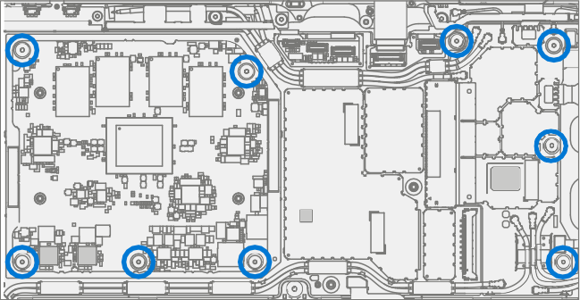
Remove screws – Using a 3IP (Torx-plus) driver remove the 9 screws securing the motherboard in the chassis.

Disconnect FPC’s – Using a plastic spudger remove the three FPCs connected to the motherboard. One on the upper right, one on the bottom right, and one on the bottom left.

Remove the left WiFi antenna – Using a 3IP (Torx-plus) driver remove the 3 screws from the upper left antenna. Lift the antenna board out of the chassis.

Remove motherboard – Using two hands remove motherboard from chassis.

Procedure - Installation (Motherboard)
Install motherboard – Using two hands align screw holes on motherboard with the chassis and place motherboard in the chassis, first aligning the USB connector into the opening and then lowering into the screw posts in the chassis.

Install screws – Using a 3IP (Torx-plus) driver install the 9 screws marked, turning each screw until finger tight then tightening by another 1/8 turn (45-degrees) or until fully fastened.
Install left WiFi antenna – Place the antenna board in the chassis making sure that the antennas touch the copper pads on the side of the PCB. Using a 3IP (Torx-plus) driver install the 3 screws securing the antenna board to the chassis. Turn each screw until finger tight then tighten by another 1/8 turn (45-degrees) or until fully fastened.

Connect FPC’s – Using a plastic spudger align and press in the three FPCs connected to the motherboard. One on the upper right, one on the bottom right, and one on the bottom left.
Connect antennas – Carefully align the coaxial cables with their connectors on the motherboard and gently press in using an IPEX tool.
Important
Each coaxial cable must go back to the same location it was removed from. The wires should be long enough to return to their original position.

Install antenna shields – Using a pair of tweezers, align the highlighted antenna shields on the motherboard, then press each one down using a finger.

Install Thermal Module – Install the thermal module as detailed in the Procedure – Installation (Thermal Module)
Install Surflink – Install the Surflink as detailed in the Procedure – Installation (Surflink).
Install Display – Install the display as detailed in the Procedure – Installation (Display).
Install rSSD – Install the rSSD as detailed in the Procedure – Installation (rSSD).
Run SDT – Power on device and connect USB drive with SDT Configuration Files. Run SDT to ensure all device features and functions operate as expected. If no further repairs are required proceed to final steps.
Battery Authentication – Authenticate new battery as detailed in step 14 on Procedure – Installation (Battery).
Chassis Replacement Process
Preliminary Requirements Required Tools and Components
Tools:
- 3IP (Torx-plus) driver
- Anti-static wrist strap (1 MOhm resistance)
- Soft ESD safe mat
- Microfiber / lint free cloth
- Isopropyl alcohol dispenser bottle (use 91% or greater IPA)
- Cotton swab
- USB drive with Surface Diagnostic Toolkit
- Spudger
- Plastic tweezers
Components:
- Chassis (Refer to Illustrated Service Parts List)
Prerequisite Steps
Important
The serial number for this device model is located on its original cover. To keep track of the device’s serial number, record it using waterproof ink on a sticker or label and apply the sticker or label to an easily accessible area on the device exterior. The serial number can't be added permanently to a replacement part. Microsoft might have provided a label for this use in the replacement part’s packaging.
- Power off device – Ensure device is powered off and disconnected from a power supply.
- General Safety – Check to make sure that general guidelines and ESD compliance steps are followed before opening device. Refer to Prior to Device Disassembly section for details.
- Position device – Place device onto a clean surface free of debris with the bottom facing up.
- Remove rSSD – Remove the rSSD as detailed in the Procedure – Removal (rSSD).
- Remove Display – Remove the display as detailed in the Procedure – Removal (Display).
- Remove Surflink – Remove the display as detailed in the Procedure – Removal (Surflink).
- Remove Thermal Module – Remove the thermal module as detailed in the Procedure – Removal (Thermal Module).
- Remove Battery – Follow steps for Procedure – Removal (Battery).
- Remove Speakers – Follow steps for Procedure – Removal (Speakers).
- Remove Buttons – Follow steps for Procedure – Removal (Buttons).
- Remove Camera Deck – Follow steps for on Procedure – Removal (Camera Deck).
- Remove Front Camera – Follow steps for on Procedure – Removal (Front Camera).
- Remove Rear Camera – Follow steps for on Procedure – Removal (Rear Camera).
- Remove Motherboard – Follow steps for on Procedure – Removal (Motherboard PCBA).
Procedure - Removal (Chassis)
- Prepare parts – Follow all removal steps in the Prerequisite Steps section of this chapter.
Procedure - Installation (Chassis)
- Remove tape – Remove tape used to retain the Coaxial Cables.
- Remove the left WiFi antenna – Using a 3IP (Torx-plus) driver remove the 3 screws from the upper left antenna. Lift the antenna board out of the chassis.
Important
Retain the screws and hardware removed during this step. They need to be reused during reassembly.

- Install Motherboard – Install the motherboard as detailed in the Procedure – Installation (Motherboard).
- Install Rear Camera – Install the Surflink as detailed in the Procedure – Installation (Rear Camera).
- Install Front Camera – Install the Surflink as detailed in the Procedure – Installation (Front Camera).
- Install Camera Deck – Install the Surflink as detailed in the Procedure – Installation (Camera Deck)
- Install Speakers – Install the Surflink as detailed in the Procedure – Installation (Speakers)
- Install Battery – Install the new battery as detailed in the Procedure – Installation (Battery)
- Install Thermal Module – Install the thermal module as detailed in the Procedure – Installation (Thermal Module)
- Install Surflink – Install the Surflink as detailed in the Procedure – Installation (Surflink).
- Install Display – Install the display as detailed in the Procedure – Installation (Display).
- Install rSSD – Install the rSSD as detailed in the Procedure – Installation (rSSD).
- Run SDT – Power on device and connect USB drive with SDT Configuration Files. Run SDT to ensure all device features and functions operate as expected.