Note
Access to this page requires authorization. You can try signing in or changing directories.
Access to this page requires authorization. You can try changing directories.
Warning
Review the General Safety Precautions and Battery Safety guidelines in their entirety before proceeding with any repair steps.
Important
Read this Guide in its entirety before starting any repairs. If at any point you're unsure or uncomfortable about performing the repairs, as detailed in this Guide, DO NOT proceed. Contact Microsoft for more support options.
Warning
Failure to follow the instructions in this Guide, use of non-Microsoft (nongenuine), incompatible, or modified replacement parts, and/or failure to use proper tools could result in serious injury, death, and/or damage to the product or other property.
Prerequisite Steps
Steps outlined in this section should be conducted prior to starting any repair on a Surface device.
Power off device – Ensure the device is powered off completely and the battery has been fully discharged. Refer to the Repair-specific precautions and warnings section for guidelines. Once discharged, the device should be disconnected from all power sources.
ESD Prevention – Ensure ESD prevention steps and general guidelines are followed prior to opening the device. Refer to the ESD Prevention section for guidelines.
Position Device – To prevent damage to the device, ensure the device is placed on a clean surface free of debris.
Non-Skid Feet Replacement Process
Preliminary Requirements
Important
Be sure to follow all special (bolded) notes of caution within each process section.
Required Tools and Components
- Tools:
- Plastic tweezers / spudger
- Isopropyl Alcohol Dispenser Bottle (use only 70% IPA)
- Cleaning swabs
- Soft ESD-safe mat
- Microfiber cloth
- Components:
- Feet (Refer to Illustrated Service Parts List)
Prerequisite Steps
- Power off device – Ensure device is powered off and has been disconnected from a power supply for at least 30 seconds.
- General Safety – Check to make sure that general guidelines and ESD compliance steps are followed prior to opening the device. Refer to Prior to Device Disassembly section for details.
- Position device – Place device onto a clean surface free of debris with the screen face down on an ESD mat and the base of the unit facing the technician.
Procedure - Removal (Non-Skid Feet)
Feet removal – Use plastic tool / spudger to lift one edge of each foot. Ensure all adhesive tape remnants and glue residue are removed. Clean the cosmetic plate foot divots with 70% Isopropyl Alcohol.

Procedure - Installation (Non-Skid Feet)
Important
Once removed, the feet must be replaced with new ones.
Position device – Place device onto a clean surface free of debris with the screen face down on an ESD mat and the base of the unit facing the technician.
Prepare new foot and press into place – To install each foot, remove protective sheet to expose adhesive on foot. Press foot into cosmetic plate divot for at least 15 seconds. Repeat for each foot.

Inspect for anomalies – Inspect each foot to ensure there's no cosmetic damage or gaps between the foot and the cosmetic plate foot divots.
Thermal Module Replacement Process
Preliminary Requirements
Important
Be sure to follow all special (bolded) notes of caution within each process section.
Required Tools and Components
- Tools:
- Plastic tweezers / spudger
- Isopropyl Alcohol Dispenser Bottle (use only 70% IPA)
- Cleaning swabs
- Metric plastic thickness gauges
- Soft ESD-safe mat
- Microfiber cloth
- 8IP (Torx-plus) driver
- 10IP (Torx-plus) driver
- H5 hex socket
- Components:
- Thermal Module (Refer to Illustrated Service Parts List)
- Fan Cover Screw 1 (131B-022D0QS) Qty. 4 (Panhead)
- Fan Cover Screw 2 (131A-01LT0QS) Qty. 4 (Flathead)
- Cosmetic Plate Screw 1 (131B-022A0QS) Qty. 2 (Short)
- Cosmetic Plate Screw 2 (131B-022D0QS) Qty. 2 (Long, towards front of unit)
- Thermal Module Standoff (13P1-4SU2U21) Qty. 1
Prerequisite Steps
- Power off device – Ensure device is powered off and has been disconnected from a power supply for at least 30 seconds.
- General Safety – Check to make sure that general guidelines and ESD compliance steps are followed prior to opening the device. Refer to Prior to Device Disassembly section for details.
- Position device – Place device onto a clean surface free of debris with the screen face down on an ESD mat and the base of the unit facing the technician.
- Remove Feet – Refer to Procedure – Removal (Non-Skid Feet) for details.
Procedure - Removal (Thermal Module)
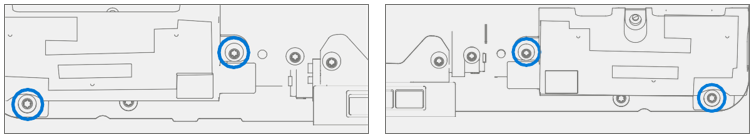
Remove cosmetic plate – Remove the 4 screws at each corner of the cosmetic plate using an 8IP (Torx-plus) driver. Using a plastic spudger, gently work around the edge of the cosmetic plate to loosen it. Then gently pull the cosmetic plate away from the unit, being careful to peel off the foam tape that connects the cosmetic plate to the fan cover underneath using the flat end of a plastic spudger.
Caution
The foam tape is located near the Microsoft logo on the cosmetic plate. Be careful when removing the foam tape from the cosmetic plate, it's delicate and easily torn.

Cleaning – Remove any adhesive tape remnants from the cosmetic plate using IPA and a cotton swab.
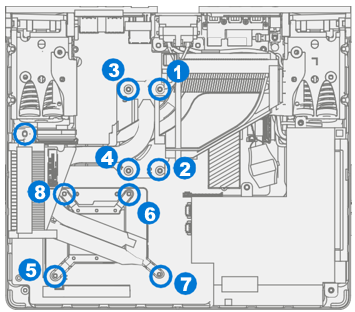
Remove fan cover
Remove the 8 marked screws from fan plate using an 8IP (Torx-plus) driver.
Important
Only remove the marked screws. Removal of screws securing fans to fan-cover isn't required.

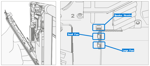
While holding the fan cover at a 45-degree angle, disconnect the two fan cables and one speaker cable from the headers on motherboard.
Caution
Cables are fragile. Be extra cautious to not damage connector cables.

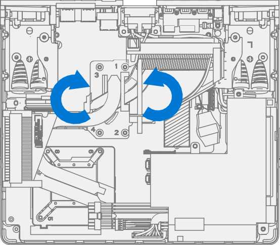
Remove thermal module
Using a H5 (Hex) socket, remove the standoff from the right side of the chassis. Using a 10IP (Torx-plus) driver, unscrew the first four captive screws (numbered 1 through 4). While holding the THM with one hand, use an 8IP (Torx-plus) driver to unscrew the final four captive screws (numbered 5 through 8).

Gently rotate the thermal module left and right a few times to break the bond with the thermal material on the CPU, GPU, and rSSD. Once the bond is broken, lift the thermal module out of the device.
Caution
Don't pull off thermal module without breaking the bond with the thermal interface materials. Doing so may cause damage to the rSSD and/or CPU and GPU.
Remove thermal material – Using a cotton swab and Isopropyl alcohol clean the thermal interface material from the CPU and GPU. Wipe down with a lint-free cloth.
Caution
Do scrub or apply too much pressure on the CPU or GPU dies. Excess pressure may cause damage to the chips.

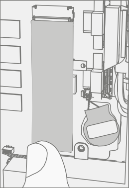
Remove thermal pad– Using your fingers remove the thermal pad on the rSSD.

Procedure - Installation (Thermal Module)
Apply new thermal material – Apply new thermal pad to the rSSD.

Install new thermal module – Position new thermal module over CPU and GPU, while holding with one hand use a 10IP (Torx-plus) driver to tighten the first four captive screws (numbered 1 through 4). Turn each screw until snug, then turn another 45-degrees (1/4 turn). Use an 8IP (Torx-plus) driver to tighten the final four captive screws (numbered 5 through 8) using the same process as above. Use a H5 (Hex) socket to install the right standoff using the process above.
Final Inspection – Prior to continuing with the reassembly, inspect the device internals to ensure no screws, foams, tape, or other foreign material has been misplaced inside the unit.
Install fan cover
While holding the fan cover at a 45-degree angle, connect the two fan cables and one speaker cable to the headers on the motherboard.
Caution
Cables are fragile. Be extra cautious to not damage connector cables. Tuck them into the fan cover as shown.

Using an 8IP (Torx-plus) driver install the 4 panhead fan cover screws (1), tightening each screw until snug and then turn another 45 degrees (1/8 turn). Repeat this process for the 4 flathead fan cover screws (2).
Important
Ensure that connector wires don't touch the fans by ensuring that the fans spin freely.

Install cosmetic plate
Align the tabs on cosmetic plate with the openings on the fan cover. Install the foam tape from the fan cover onto the back of the cosmetic plate and fit the two parts together.
Caution
The foam tape should be located near the Microsoft logo on the cosmetic plate. Be careful when installing foam tape on the cosmetic plate, it's delicate.

Using a 8IP (Torx-plus) driver install the 4 screws at the corners of the C-Cover, tightening each screw until snug and then turn another 45 degrees (1/8 turn).

Power on device – Carefully place device top side up. Connect device to power supply and power on.
Run SDT – Run SDT to ensure all device features and functions operate as expected.
Install Feet – Refer to Procedure – Installation (Feet) for details.
Power Supply Replacement Process
Preliminary Requirements
Important
Be sure to follow all special (bolded) notes of caution within each process section.
Required Tools and Components
- Tools
- Plastic tweezers / spudger
- Isopropyl Alcohol Dispenser Bottle (use only 70% IPA)
- Cleaning swabs
- Metric plastic thickness gauges
- Soft ESD-safe mat
- Microfiber cloth
- 8IP (Torx-plus) driver
- H5 (Hex) socket driver
- Digital Multimeter
- Components
- Power Supply Unit (Refer to Illustrated Service Parts List)
- PSU Standoff (13P1-4SU2U21) Qty. 1
- PSU Screw (131B-022D0QS) Qty. 1
- Power Plug Screw (131B-022D0QS) Qty. 1
- Power Plug Standoff (13E5-3TN0C01) Qty. 1
- Hinge Cover Screws (131B-022D0QS) Qty. 1
Prerequisite Steps
- Power off device – Ensure device is powered off and has been disconnected from a power supply for at least 30 seconds.
- General Safety – Check to make sure that general guidelines and ESD compliance steps are followed prior to opening the device. Refer to Prior to Device Disassembly section for details.
- Position device – Place device onto a clean surface free of debris with the screen face down on an ESD mat and the base of the unit facing the technician.
- Remove Feet – Refer to Procedure – Removal (Non-Skid Feet) for details.
- Remove Thermal Module – Refer to Procedure – Removal (Thermal Module) for details.
Procedure - Removal (Power Supply)
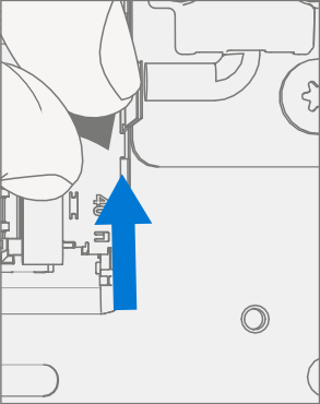
Remove right hinge cover – Using an 8IP (Torx-plus) driver, remove the screw securing the plastic hinge cover from the right hinge. Using a plastic spudger, lift the hinge cover from the hinge. Finally, use isopropyl alcohol to clean any residue.

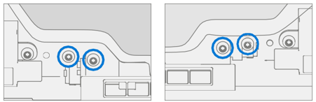
Remove power plug – Using an 8IP (Torx-plus) driver remove the right screw, using a H5 (Hex) socket remove the left standoff.

Remove power supply
Using an 8IP (Torx-plus) driver remove the top screw securing the power supply to the chassis. Using a H5 (Hex) socket remove the bottom left standoff.

Lift the power supply out of the chassis, rotating towards the back of the unit. Gently pull out the small connector underneath the larger one. Depress the clip on the large connector to fully disconnect the power supply from the chassis.

Procedure - Installation (Power Supply)
Inspect power supply cables – Before installation, check cables on power supply for any abrasion or damage. Any damage to power supply cables require the power supply to be replaced.
Install new power supply
Connect large connector to the motherboard by pressing in until there's a small click. While holding the power supply, carefully insert the small connector into its plug.
Important
Both connectors are keyed and may only be inserted in one direction. Be careful to align connectors properly before pressing them into the motherboard to avoid damage to the motherboard.

Using an 8IP (Torx-plus) driver install the top screw, tightening the screw until snug and then turn another 1/8 turn (45 degrees). Repeat this process for the bottom left standoff using a H5 (Hex) socket.
Caution
Ensure the wires are pulled away from screw hole when installing screws. Damage to the casing of the wires requires PSU replacement.

Install power plug – Using an 8IP (Torx-plus) driver install the right screw, tightening until snug and then turn another 45 degrees (1/8 turn). Repeat this process for the left standoff using a H5 (Hex) socket.

Install right hinge cover – Align PSU wires as shown in image below. Then using an 8IP (Torx-plus) driver, secure using the hinge cover screw, tightening until snug and then turn another 45 degrees (1/8 turn).
Warning
Take care not to pinch the wires between the motherboard and hinge cover. This could damage the wires and the motherboard and cause an electrical fault.

Install thermal module – Refer to Procedure – Installation (Thermal Module) for details.
Perform continuity test – A continuity test must be performed after the device is reassembled and before it's returned to the user. The continuity test shall be performed from each of the three pins on the AC inlet to an exposed metal part of the chassis (ground). For chassis ground, insert a good USB cable into a USB port and use the metal shell of the connector on the opposite end of the cable as the contact point for the chassis (ground).
Important
After the repair process, any device that incorporates an internal power supply that connects to AC mains, may present a shock hazard to the user. This may be caused by conditions such as improper cable routing, pinched wires, foreign objects, solder bridges, debris, etc.
Important
If the device fails any portion of this test, remove the PSU and inspect the cables. If the cables are damaged or if the PSU continues to fail, replace the PSU.
a. Measure the resistance between the ground (center) pin to chassis (ground). A resistance of less than 0.5 ohms shall be measured.

b. Measure the resistance between the neutral (right) pin to chassis (ground). A resistance of more than 50k ohms shall be measured.

c. Measure the resistance between the live (left) pin to chassis (ground). A resistance of more than 50k ohms shall be measured.

Power on device – Carefully place device top side up. Connect device to power supply and power on.
Run SDT – Run SDT to ensure all device features and functions operate as expected.
Install feet – Refer to Procedure – Installation (Feet) for details.
rSSD Replacement Process
Preliminary Replacement Requirements
Important
Be sure to follow all special (bolded) notes of caution within each process section.
Required Tools and Components
- Tools
- Plastic tweezers / spudger
- Anti-static wrist strap (1 MOhm resistance)
- Isopropyl Alcohol Dispenser Bottle (use only 70% IPA)
- Cleaning swabs
- Metric plastic thickness gauges
- Non-Metallic ruler (Amazon Example)
- 3IP (Torx-plus) driver
- USB Thumb drive with SDT
- Surface Power Supply
- Soft ESD-safe mat
- Microfiber cloth
- Components
- rSSD (Refer to Illustrated Service Parts List) if replacing
- rSSD Screw (13N4-10N1S11, Alt. 13N4-10N1S12) Qty. 1
Prerequisite Steps
- Power off device – Ensure device is powered off and has been disconnected from a power supply for at least 30 seconds.
- General Safety – Check to make sure that general guidelines and ESD compliance steps are followed prior to opening the device. Refer to Prior to Device Disassembly section for details.
- Position device – Place device onto a clean surface free of debris with the screen face down on an ESD mat and the base of the unit facing the technician.
- Remove Feet – Refer to Procedure – Removal (Non-Skid Feet) for details.
- Remove Thermal Module – Refer to Removal (Thermal Module) for details.
Procedure - Removal (rSSD)
Remove thermal pad – Using your fingers remove the thermal pad on the rSSD.
Remove rSSD screw – Using a 3IP (Torx-plus) driver remove the screw securing the rSSD.

Remove rSSD – Lift the rSSD to 15 degrees and pull the rSSD out of the connector.

Procedure - Installation (rSSD)
Insert rSSD – Insert the connector end of the rSSD into the receptacle on the motherboard at 15-degree angle from horizontal.

Install rSSD screw – Using a 3IP (Torx-plus) driver install the rSSD screw. Turn until just snug and seated, and then turn another 45 degrees (1/8 turn) or until fully fastened.

Install thermal pad – Install new thermal interface material on top of rSSD.

Install thermal module – Refer to Procedure – Installation (Thermal Module) for details.
Power on device – Carefully place device on its base. Connect device to power supply, and power on.
Imaging – Image the new rSSD by using a BMR Imaging USB drive specific to the device model.
Important
Refer to Surface imaging process - Surface Imaging Tools
Run SDT – Run SDT to ensure all device features and functions operate as expected.
Install feet – Refer to Procedure – Installation (Feet) for details.
Motherboard Replacement Process
Preliminary Requirements
Important
Be sure to follow all special (bolded) notes of caution within each process section.
Required Tools and Components
- Tools
- Plastic tweezers / spudger
- Anti-static wrist strap (1 MOhm resistance)
- Isopropyl Alcohol Dispenser Bottle (use only 70% IPA)
- Cleaning swabs
- Metric plastic thickness gauges
- 3IP (Torx-plus) driver
- 8IP (Torx-plus) driver
- H5 (Hex) socket
- USB Thumb drive with SDT
- Surface Power Supply
- Soft ESD-safe mat
- Microfiber cloth
- Components
- Motherboard (Refer to Illustrated Service Parts List)
- Hinge Cover Screws (131B-022D0QS) Qty. 2
- Motherboard Screws (131B-02150QS) Qty. 3
Prerequisite Steps
- Power off device – Ensure device is powered off and has been disconnected from a power supply for at least 30 seconds.
- General Safety – Check to make sure that general guidelines and ESD compliance steps are followed prior to opening the device. Refer to Prior to Device Disassembly section for details.
- Position device – Place device onto a clean surface free of debris with the screen face down on an ESD mat and the base of the unit facing the technician.
- Remove Feet – Refer to Procedure – Removal (Non-Skid Feet) for details.
- Remove Power Supply – Refer to Procedure – Removal (Power Supply) for details.
- Remove Thermal Module – Refer to Procedure – Removal (Thermal Module) for details.
- Remove rSSD – Refer to Procedure – Removal (rSSD) for details.
Procedure - Removal (Motherboard)
Remove hinge cover – Using an 8IP (Torx-plus) driver, remove the two screws securing the plastic left hinge cover to the left hinge. Using a plastic spudger, lift the hinge cover from the hinge. Finally, use isopropyl alcohol to clean any residue.

Disconnect display cables – Using a plastic spudger lift the locking bar from the three ribbon cables connected to the motherboard, slide them back, and lift them out.

Disconnect audio port – Using a pair of plastic tweezers, lift the white locking tab on the connector, then remove the ribbon cable for the audio port.

Remove motherboard screws – While holding the motherboard in place with one hand, use an 8IP (Torx-plus) driver, remove the 3 screws securing the motherboard to the chassis.

Remove the motherboard – Using two hands remove the motherboard from the chassis.
Procedure - Installation (Motherboard)
Install new motherboard – Place the new motherboard in the chassis using two hands. Align the motherboard with the screw holes in the chassis.
Install motherboard screws – While securing the motherboard with one hand, use an 8IP (Torx-plus) driver to install the 3 motherboard screws, tightening until finger tight. Then turn another 45 degrees (1/8 turn) or until fully fastened.

Connect display connectors – Position the cable over the connector and slide it into place. Push the locking tab down to secure the connector in place. Repeat process for the remaining two ribbon cables.

Connect audio port – Using a pair of plastic tweezers position and slide the ribbon cable into the audio port. Then press down the locking tab.

Install hinge covers and screws – Using an 8IP (Torx-plus) driver install the 2 hinge screws securing the plastic hinge cover to the left hinge. Tighten until just snug and seated, then turn another 45 degrees (1/8 turn) or until fully fastened.

Install rSSD – Refer to Procedure – Installation (rSSD) for details.
Install thermal module – Refer to Procedure – Installation (Thermal Module) for details.
Install power supply – Refer to Procedure – Installation (Power Supply) for details.
Power on device – Carefully place device top side up. Connect device to power supply, and power on.
Run SDT – Run SDT to ensure all device features and functions operate as expected.
Install Feet – Refer to Feet installation on Procedure - Installation (Non-Skid Feet) for details.
Display Replacement Process
Preliminary Requirements
Important
Be sure to follow all special (bolded) notes of caution within each process section.
Required Tools and Components
- Tools
- Plastic tweezers / spudger
- Plastic card tool (example iFixit Plastic Card)
- Anti-static wrist strap (1 MOhm resistance)
- Isopropyl Alcohol Dispenser Bottle (use only 70% IPA)
- Cleaning swabs
- Metric plastic thickness gauges
- 6IP (Torx-plus) driver
- 9IP (Torx-plus)
- USB Thumb drive with SDT
- Surface Power Supply
- Soft ESD-safe mat
- Microfiber cloth
- Components
- Display Module (Refer to Illustrated Service Parts List)
- WiFi Antenna Screws (131B-01WU0QS) Qty. 12
- End Cap Screws (131A-01K20QS) Qty. 2
- Display Hinge Screws (131A-01LU0QS) Qty. 9
Prerequisite Steps
- Power off device – Ensure device is powered off and has been disconnected from a power supply for at least 30 seconds.
- General Safety – Check to make sure that general guidelines and ESD compliance steps are followed prior to opening the device. Refer to Prior to Device Disassembly section for details.
- Position device – Place device onto a clean surface free of debris with the screen face down on an ESD mat and the base of the unit facing the technician.
Procedure - Removal (Display)
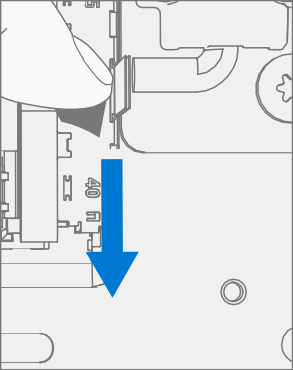
Remove hinge cover – Squeeze the top of the hinge cover with thumbs pressed firmly along the back for leverage. There should be an audible click as the plastic retaining tabs release from the back of the display. Rotate the hinge cover 15 degrees, then press bottom of the cover to release the bottom clips. Lift display hinge cover up and out.
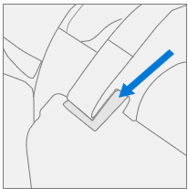
Caution
The plastic tabs on the hinge cover are fragile. If any tabs break, the hinge cover must be replaced. Example of a damaged hinge below.

Remove screws – Using a 6IP (Torx-plus) driver remove the 12 screws marked below. Retain the two end caps on the left and right, and the plastic stiffening bar in the middle.
Important
The copper tape on the antenna boards is very fragile. Take extra caution to not tear it during screw removal.

Remove hinge plate – Carefully peel up the copper tape from the two antennas on the left and right of the hinge. Position the antennas so the plate can be lifted away without disturbing the antenna wires. Lift hinge plate away from device.

Remove display connectors – Pull the tab on each of the 4 connectors to disconnect them from the display.
Remove hinge screws – While supporting the bottom of the unit with one hand, use a 9IP (Torx-plus) driver to remove the nine highlighted screws and separate the display from the rest of the unit.

Procedure - Installation (Display)
Position hinge over new display – Align the screw holes on the new Display with the holes on the hinge.
Install new hinge screws – While supporting the bottom of the unit with one hand, use a 9IP (Torx-plus) driver to install the 9 display hinge screws as marked below. Tighten each screw until snug, then turn each screw another 1/8 turn (45 degrees) or until fully fastened.

Install display connectors – Slide one of the connectors into the proper receptacle on the display. Make sure the connector is fully seated. Repeat for the remaining three FPC connectors.
Install hinge plate – Carefully move the antennas so they do not interfere with the hinge plate and position the hinge plate in place. Position WiFi antennas over holes. Using a 6IP (Torx-plus) Driver install 2 WiFi antenna screws as indicated below. Tighten each screw until snug, then turn each screw another 1/8 turn (45 degrees) or until fully fastened.
Important
There is a notch on the hinge to accommodate the tabs of the hinge plate.

Secure WiFi antennas
Position the two end caps on the left and right over the WiFi antennas. Using a 6IP (Torx-plus) Driver install 2 WiFi antenna screws as indicated below. Tighten each screw until snug, then turn each screw another 1/8 turn (45 degrees) or until fully fastened.
Install copper tape over each WiFi antenna, making sure to cover the antenna and the hinge plate.
Caution
The copper tape on the antenna boards is very fragile. Take extra caution to not tear it during screw installation.

Using a 6IP (Torx-plus) Driver install the 4 remaining WiFi antenna screws as indicated below. Tighten each screw until snug, then turn each screw another 1/8 turn (45 degrees) or until fully fastened.
Install cover guide bar screws – Position the cover guide bar retained from step 2 of Procedure – Removal (Display) over the center holes of the hinge plate. Using a 6IP (Torx-plus) Driver install the 2 WiFi screws marked below. Tighten each screw until snug, then turn each screw another 1/8 turn (45 degrees) or until fully fastened.

Install Hinge Cover – Slot in the bottom of the hinge cover first, then align the plastic tabs with the appropriate holes along the top of the hinge. Squeeze the top of the hinge cover with thumbs pressed firmly along the back for leverage and slot top into the place. There should be an audible click as the plastic retaining tabs slot into place in the display.
Caution
The plastic tabs on the hinge cover are fragile. If any tabs break, the hinge cover must be replaced. Example of a damaged hinge below.

Power on device – Carefully place device top side up. Connect device to power supply, and power on.
Run SDT – Run SDT to ensure all device features and functions operate as expected.